
Page 72 - Steam Turbines Design, Applications, and Rerating
P. 72
Bearings for Mechanical Drive Turbines 53
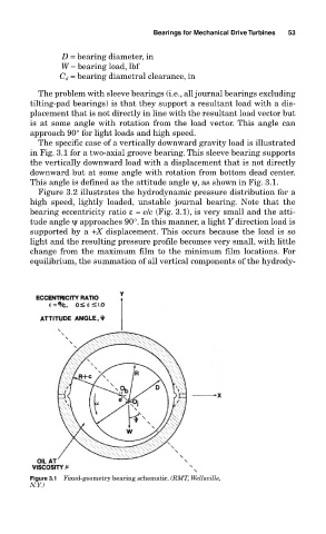
D = bearing diameter, in
W = bearing load, lbf
C d = bearing diametral clearance, in
The problem with sleeve bearings (i.e., all journal bearings excluding
tilting-pad bearings) is that they support a resultant load with a dis-
placement that is not directly in line with the resultant load vector but
is at some angle with rotation from the load vector. This angle can
approach 90° for light loads and high speed.
The specific case of a vertically downward gravity load is illustrated
in Fig. 3.1 for a two-axial groove bearing. This sleeve bearing supports
the vertically downward load with a displacement that is not directly
downward but at some angle with rotation from bottom dead center.
This angle is defined as the attitude angle ψ, as shown in Fig. 3.1.
Figure 3.2 illustrates the hydrodynamic pressure distribution for a
high speed, lightly loaded, unstable journal bearing. Note that the
bearing eccentricity ratio ε= e/c (Fig. 3.1), is very small and the atti-
tude angle ψ approaches 90°. In this manner, a light Y direction load is
supported by a +X displacement. This occurs because the load is so
light and the resulting pressure profile becomes very small, with little
change from the maximum film to the minimum film locations. For
equilibrium, the summation of all vertical components of the hydrody-
Figure 3.1 Fixed-geometry bearing schematic. (RMT, Wellsville,
N.Y.)