
Page 96 - Steam Turbines Design, Applications, and Rerating
P. 96
Bearings for Mechanical Drive Turbines 77
The AMB typically includes a stator and a journal. The journal is
assembled on a portion of the rotating shaft and is surrounded by the
stator. In an eight-pole design, the stator is separated into four sectors.
Current circulates to each magnetic coil, creating a flux within each
bearing sector. This creates a magnetic force in each sector that can be
varied without affecting the other sectors, allowing independent con-
trol and physical separation.
Each sector (two poles) exerts an attractive force on the journal. Two
opposite sectors of poles at each axis are used to center the journal.
These forces, which can be varied by current, provide the stability, stiff-
ness, and damping control to the bearing.
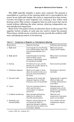
TABLE 3.1 Comparison of Magnetic vs. Hydrodynamic Bearings
Requirement Magnetic bearings Hydrodynamic bearings
1. High loads Load capacity low, but bearing High load capacity
area could be higher than with (except at low speeds)
conventional bearings (see 3
below)
2. High speeds Limited mainly by bursting Shear losses can become
speed of shaft; system significant
response to disturbance must
be considered carefully
3. Sealing No lubricant to seal, and the Seals must be provided
bearing can usually operate in
the process fluid
4. Unbalance response Shaft can be made to rotate Synchronous vibration
about its inertial center, so no inevitable
dynamic load transmitted to
the frame
5. Dynamic loads Damping can be tuned, but Damping due to squeeze
adequate response at high effects is high, and
frequency may not be possible virtually instantaneous
in its effect
6. Losses Very low rotational losses at Hydrodynamic and
shaft, and low power pumping losses can be
consumption in magnets/ significant, particularly
electronics at high speeds
7. Condition monitoring Rotor position and bearing Vibration and
loads may be obtained temperature instrumen-
from the control system tation can be added
8. Reliability and Magnets and transducers do Very reliable with low
maintainability not contact the shaft so maintenance require-
operating damage is unlikely; ments
electronics may be sited in any
convenient position
SOURCE: MTI, Inc., Latham, N.Y.