
Page 179 - Structural Steel Designers Handbook AISC, AASHTO, AISI, ASTM, and ASCE-07 Design Standards
P. 179
Brockenbrough_Ch04.qxd 9/29/05 5:09 PM Page 4.7
BUILDING CODES, LOADS, AND FIRE PROTECTION*
BUILDING CODES, LOADS, AND FIRE PROTECTION 4.7
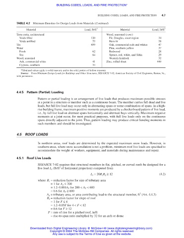
TABLE 4.2 Minimum Densities for Design Loads from Materials (Continued)
Material Load, lb/ft 3 Material Load, lb/ft 3
Terra cotta, architectural Wood, seasoned (cont.)
Voids filled 120 Fir, Douglas, coast region 34
Voids unfilled 72 Hem fir 28
Tin 459 Oak, commercial reds and whites 47
Water Pine, southern yellow 37
Fresh 62 Redwood 28
Sea 64 Spruce, red, white, and Sitka 29
Wood, seasoned Western hemlock 32
Ash, commercial white 41 Zinc, rolled sheet 449
Cypress, southern 34
*Tabulated values apply to solid masonry and to the solid portion of hollow masonry.
Source: From Minimum Design Loads for Buildings and Other Structures, SEI/ASCE 7-02, American Society of Civil Engineers, Reston, Va.,
with permission.
4.4.5 Pattern (Partial) Loading
Pattern or partial loading is an arrangement of live loads that produces maximum possible stresses
at a point in a structure or member such as a continuous beam. The member carries full dead and live
loads, but full live load may occur only in alternating spans or some combination of spans. In a high-
rise building frame, maximum positive moments are produced by a checkerboard pattern of live load,
i.e., by full live load on alternate spans horizontally and alternate bays vertically. Maximum negative
moments at a joint occur, for most practical purposes, with full live loads only on the continuous
spans directly adjacent to the joint. Thus, pattern loading may produce critical bending moments in
such members and should be investigated.
4.5 ROOF LOADS
In northern areas, roof loads are determined by the expected maximum snow loads. However, in
southern areas, where snow accumulation is not a problem, minimum roof live loads are specified to
accommodate the weight of workers, equipment, and materials during maintenance and repair.
4.5.1 Roof Live Loads
SEI/ASCE 7-02 requires that structural members in flat, pitched, or curved roofs be designed for a
2
live load L r (lb/ft of horizontal projection) computed from
L r = 20R 1 R 2 ≥ 12 (4.2)
where R 1 = reduction factor for size of tributary area
= 1 for A T ≤ 200
= 1.2–0.001A T for 200 < A T < 600
= 0.6 for A T ≥ 600
2
A T = tributary area, or area contributing load to the structural member, ft (Art. 4.4.3)
R 2 = reduction factor for slope of roof
= 1 for F ≤ 4
= 1.2–0.05F for 4 < F < 12
= 0.6 for F ≥ 12
F = rate of rise for a pitched roof, in/ft
= rise-to-span ratio multiplied by 32 for an arch or dome
Downloaded from Digital Engineering Library @ McGraw-Hill (www.digitalengineeringlibrary.com)
Copyright © 2004 The McGraw-Hill Companies. All rights reserved.
Any use is subject to the Terms of Use as given at the website.