
Page 182 - Structural Steel Designers Handbook AISC, AASHTO, AISI, ASTM, and ASCE-07 Design Standards
P. 182
Brockenbrough_Ch04.qxd 9/29/05 5:09 PM Page 4.10
BUILDING CODES, LOADS, AND FIRE PROTECTION*
4.10 CHAPTER FOUR
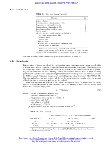
TABLE 4.4 Live Load Element Factor, K LL
Element K LL *
Interior columns 4
Exterior columns without cantilever slabs 4
Edge columns with cantilever slabs 3
Corner columns with cantilever slabs 2
Edge beams without cantilever slabs 2
Interior beams 2
All other members not identified above, including: 1
Edge beams with cantilever slabs
Cantilever beams
One-way slabs
Two-way slabs
Members without provisions for continuous shear
transfer normal to their span
*In lieu of the values above, K LL is permitted to be calculated.
Source: From Minimum Design Loads for Buildings and Other Structures,
SEI/ASCE 7-02, American Society of Civil Engineers, Reston, Va., with permission.
This roof live load can be conveniently summarized as shown in Table 4.5.
4.5.2 Snow Loads
Determination of design snow loads for roofs is often based on the maximum ground snow load in
a 50-year mean recurrence period (2% probability of being exceeded in any year). This load, or data
for computing it from an extreme-value statistical analysis of weather records of snow on the ground,
may be obtained from the local building code or the National Weather Service. Maps showing
ground snow loads for various regions are presented in model building codes and standards, such as
the ASCE standard, “Minimum Design Loads for Buildings and Other Structures” (SEI/ASCE 7-02).
The map scales, however, may be too small for use for some regions, especially where the amount
of local variation is extreme or high country is involved.
Some building codes and SEI/ASCE 7-02 specify an equation that takes into account the conse-
quences of a structural failure in view of the end use of the building to be constructed and the wind
exposure of a flat (low-slope) roof:
(4.3)
p f = 0.7C e C t Ip g
where C e = wind exposure factor (Table 4.6)
C t = thermal effects factor (Table 4.7)
I = importance factor for end use (Table 4.8)
p f = roof snow load, lb/ft 2
= Ip g when p g ≤ 20 lb/ft 2
= 20I when p g > 20 lb/ft 2
p g = ground snow load for 50-year recurrence period, lb/ft 2
TABLE 4.5 Roof Live Loads
2
Tributary loaded area (A t ) in ft for any structural member
Roof slope, F:12 A t ≤ 200 200 < A t < 600 A t ≥ 600
F ≤ 4 20 20 (1.2–0.001 A t ) 12
4 < F < 12 20 (1.2–0.05F) 20 (1.2–0.001 A t ) (1.2–0.05F) ≥ 12 12
F ≥ 12 12 12 12
Source: From Metal Buildings System Manual, 2002, Metal Buildings Manufacturers Association,
Cleveland, Ohio, with permission.
Downloaded from Digital Engineering Library @ McGraw-Hill (www.digitalengineeringlibrary.com)
Copyright © 2004 The McGraw-Hill Companies. All rights reserved.
Any use is subject to the Terms of Use as given at the website.