
Page 312 - Structural Steel Designers Handbook AISC, AASHTO, AISI, ASTM, and ASCE-07 Design Standards
P. 312
Brockenbrough_Ch06.qxd 9/29/05 5:15 PM Page 6.34
DESIGN OF BUILDING MEMBERS
6.34 CHAPTER SIX
4
W14 × 426 with I cx = 6600 in will be selected for the column. At the top of the column, where there
is no column above the floor, the relative column–beam stiffness is
/(13
IL )
G = ∑(/ c = 6600 12 − ) 3 = . 049
c
A
IL )
∑(/ 112 .8
b b
At the column bottom, with a W14 × 426 column below,
IL )
3
12
G = ∑(/ c = 2 × 6600 /(13 − ) = .098
c
B
∑(/ b 112 .8
IL )
b
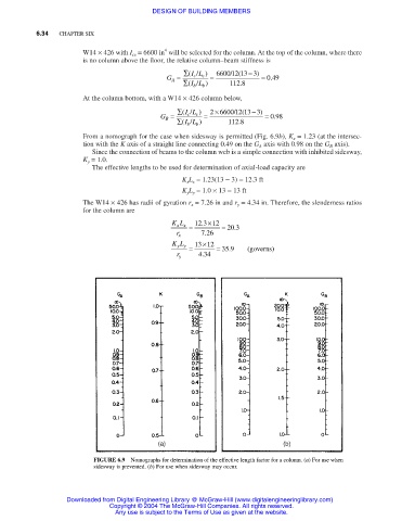
From a nomograph for the case when sidesway is permitted (Fig. 6.9b), K x = 1.23 (at the intersec-
tion with the K axis of a straight line connecting 0.49 on the G A axis with 0.98 on the G B axis).
Since the connection of beams to the column web is a simple connection with inhibited sidesway,
K y = 1.0.
The effective lengths to be used for determination of axial-load capacity are
K x L x = 1.23(13 − 3) = 12.3 ft
K y L y = 1.0 × 13 = 13 ft
The W14 × 426 has radii of gyration r x = 7.26 in and r y = 4.34 in. Therefore, the slenderness ratios
for the column are
KL = 12 3 . ×12 = 20 3 .
xx
.
r x 726
KL = 13 ×12 = 35 9 . (governs)
yy
.
r y 434
FIGURE 6.9 Nomographs for determination of the effective length factor for a column. (a) For use when
sidesway is prevented. (b) For use when sidesway may occur.
Downloaded from Digital Engineering Library @ McGraw-Hill (www.digitalengineeringlibrary.com)
Copyright © 2004 The McGraw-Hill Companies. All rights reserved.
Any use is subject to the Terms of Use as given at the website.