
Page 307 - Structural Steel Designers Handbook AISC, AASHTO, AISI, ASTM, and ASCE-07 Design Standards
P. 307
Brockenbrough_Ch06.qxd 9/29/05 5:15 PM Page 6.29
DESIGN OF BUILDING MEMBERS
DESIGN OF BUILDING MEMBERS 6.29
The W14 × 22 beam did not satisfy the vibration criteria. It is suggested that the W14 × 22 be
replaced with a W16 × 26 beam that results in an acceleration limit of 0.49%, even though the flex-
ural strength of this section is adequate.
6.14 EXAMPLE—LRFD FOR COMPOSITE BEAM WITH
CONCENTRATED LOADS AND END MOMENTS
The general information for design of a floor system is the same as that given in Art. 6.14. In this
example, a girder of A992 steel is to support the floorbeams. (Deck ribs are parallel to the girder.)
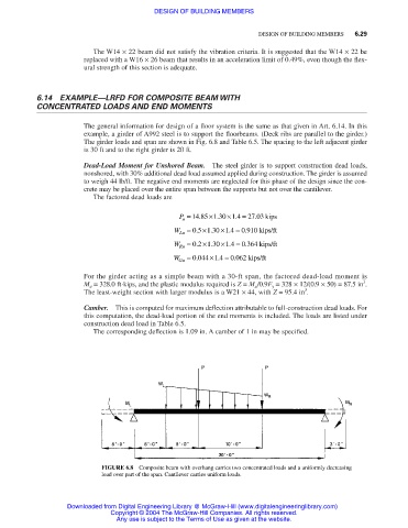
The girder loads and span are shown in Fig. 6.8 and Table 6.5. The spacing to the left adjacent girder
is 30 ft and to the right girder is 20 ft.
Dead-Load Moment for Unshored Beam. The steel girder is to support construction dead loads,
nonshored, with 30% additional dead load assumed applied during construction. The girder is assumed
to weigh 44 lb/ft. The negative end moments are neglected for this phase of the design since the con-
crete may be placed over the entire span between the supports but not over the cantilever.
The factored dead loads are
P = 14 85 ×1 30 ×1 4 = 27 03 kips
.
.
.
.
u
W = 05 ×130 ×14 = 0910 kips/ft
.
.
.
.
Lu
W Ru = 02 ×130 ×14 = 0364 kips/ft
.
.
.
.
.
.
.
W = 0 044 ×1 4 = 0 062 kips/ft
Gu
For the girder acting as a simple beam with a 30-ft span, the factored dead-load moment is
3
M u = 328.0 ft⋅kips, and the plastic modulus required is Z = M u /0.9F y = 328 × 12/(0.9 × 50) = 87.5 in .
3
The least-weight section with larger modulus is a W21 × 44, with Z = 95.4 in .
Camber. This is computed for maximum deflection attributable to full-construction dead loads. For
this computation, the dead-load portion of the end moments is included. The loads are listed under
construction dead load in Table 6.5.
The corresponding deflection is 1.09 in. A camber of 1 in may be specified.
FIGURE 6.8 Composite beam with overhang carries two concentrated loads and a uniformly decreasing
load over part of the span. Cantilever carries uniform loads.
Downloaded from Digital Engineering Library @ McGraw-Hill (www.digitalengineeringlibrary.com)
Copyright © 2004 The McGraw-Hill Companies. All rights reserved.
Any use is subject to the Terms of Use as given at the website.