
Page 308 - Structural Steel Designers Handbook AISC, AASHTO, AISI, ASTM, and ASCE-07 Design Standards
P. 308
Brockenbrough_Ch06.qxd 9/29/05 5:15 PM Page 6.30
DESIGN OF BUILDING MEMBERS
6.30 CHAPTER SIX
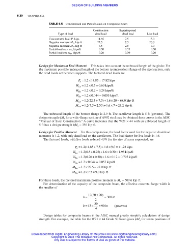
TABLE 6.5 Concentrated and Partial Loads on Composite Beam
Construction Superimposed
Type of load dead load dead load Live load
Concentrated load P, kips 14.85 7.5 15.0
Negative moment M L , kip⋅ft 22.5 7.5 20.0
Negative moment M R , kip⋅ft 7.5 2.5 7.0
Partial-load start w L , kips/ft 0.50 0.75 0.50
Partial-load end w R , kips/ft 0.20 0.30 0.20
Design for Maximum End Moment. This takes into account the unbraced length of the girder. For
the maximum possible unbraced length of the bottom (compression) flange of the steel section, only
the dead loads act between supports. The factored dead loads are
=
.
.
P = 1 2 . ×14 85 17 82 kips
u
× .
= .
W = 12 05 060 kips/ft
.
Lu
×
W Ru = 12 02 . = 024 kips/ft
.
.
.
.
× .
W = 1 2 0 044 = 0 053 kips/ft
Gu
×
.(
.
M Lu = 12 225 . + 75 . ) +16 20 = 680 . kip ⋅ft
×
=
+ .
.
.( .
M Ru = 12 75 250) +16 7 = 23 2. kip ⋅ft
The unbraced length of the bottom flange is 2.9 ft. The cantilever length is 5 ft (governs). The
design strength φM n for a wide-flange section of A992 steel may be obtained from curves in the AISC
“Manual of Steel Construction.” A curve indicates that the W21 × 44 with an unbraced length of
5 ft has a design strength φM n = 356 kip⋅ft.
Design for Positive Moment. For this computation, the load factor used for the negative dead-load
moments is 1.2, with only dead load on the cantilevers. The load factor for live loads is 1.6.
The factored loads, with live loads reduced 40% for the size of areas supported, are
×
+
.
.
P = 12 1485 75) +16 90 = 4122 kips
.
.
.
.(
u
=
×
+
.
.
.
.
W = 12 05 075) +16 030 198 kips/ft
.(
.
Lu
×
+
.
.
W Ru = 12 020 030) +16 012 = 0792 kips/ft
.
.
.
.(
×
W Gu = 1 2 0 044 = 0 053 kips/ft
.
.
.
=
×
⋅
.
.
M Lu = 1 2 22 5 = 27 0 kip ft
.
⋅
×
=
.
M Ru = 12 75 90 kip ft
.
.
For these loads, the factored maximum positive moment is M u = 509.6 kip⋅ft.
For determination of the capacity of the composite beam, the effective concrete flange width is
the smaller of
(
b = 12 30 + 20) = 300 in
2
b = 12 × 30 = 90 in (governs)
4
Design tables for composite beams in the AISC manual greatly simplify calculation of design
strength. For example, the table for the W21 × 44 Grade 50 beam gives φM n for seven positions of
Downloaded from Digital Engineering Library @ McGraw-Hill (www.digitalengineeringlibrary.com)
Copyright © 2004 The McGraw-Hill Companies. All rights reserved.
Any use is subject to the Terms of Use as given at the website.