
Page 324 - Structural Steel Designers Handbook AISC, AASHTO, AISI, ASTM, and ASCE-07 Design Standards
P. 324
Brockenbrough_Ch07.qxd 9/29/05 5:16 PM Page 7.8
FLOOR AND ROOF SYSTEMS
7.8 CHAPTER SEVEN
distribution system. When the topping is designed to act compositely with the plank, however,
careful consideration must be given to the effects of these embedded items.
Dead-Load Deflection of Concrete Plank. In design of prestressed-concrete planks, the prestressing
load balances a substantial portion of the dead load. As a result, relatively small dead-load deflections
occur. For planks subjected to significant superimposed dead-load conditions of a sustained nature,
for example, perimeter plank supporting an exterior masonry wall, additional prestressing to com-
pensate for the added dead load, or some other stiffening method, is required to prevent large initial
and creep deflections of the plank.
Diaphragm Action of Concrete-Plank Systems. The diaphragm action of a floor deck composed
of precast-concrete planks can be enhanced by making field-welded connections between steel
embedments located intermittently along the shear keys of adjacent planks. Additional diaphragm
strength may be required in certain situations, such as when large floor-deck openings are present
(see “Diaphragm Action of Metal-Deck Systems” in Art. 7.1).
Attachments of Concrete Plank to Framing. Precast-concrete planks are attached to and provide
lateral bracing for supporting steel framing. A typical method of attachment is a field-welded con-
nection between the supporting steel and steel embedments in the precast planks.
7.3 CAST-IN-PLACE CONCRETE SLABS
Use of cast-in-place concrete for floor decks in steel-framed construction is a traditional approach
that is seldom used today because of the advent of metal deck and spray-on fire protection. For one
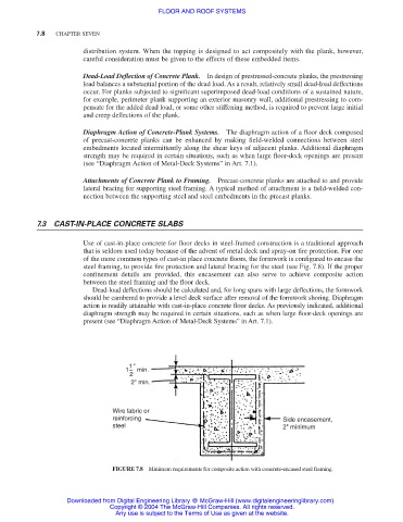
of the more common types of cast-in place concrete floors, the formwork is configured to encase the
steel framing, to provide fire protection and lateral bracing for the steel (see Fig. 7.8). If the proper
confinement details are provided, this encasement can also serve to achieve composite action
between the steel framing and the floor deck.
Dead-load deflections should be calculated and, for long spans with large deflections, the formwork
should be cambered to provide a level deck surface after removal of the formwork shoring. Diaphragm
action is readily attainable with cast-in-place concrete floor decks. As previously indicated, additional
diaphragm strength may be required in certain situations, such as when large floor-deck openings are
present (see “Diaphragm Action of Metal-Deck Systems” in Art. 7.1).
1"
1– min.
2
2" min.
Wire fabric or
reinforcing Side encasement,
steel 2" minimum
FIGURE 7.8 Minimum requirements for composite action with concrete-encased steel framing.
Downloaded from Digital Engineering Library @ McGraw-Hill (www.digitalengineeringlibrary.com)
Copyright © 2004 The McGraw-Hill Companies. All rights reserved.
Any use is subject to the Terms of Use as given at the website.