
Page 357 - Structural Steel Designers Handbook AISC, AASHTO, AISI, ASTM, and ASCE-07 Design Standards
P. 357
Brockenbrough_Ch08.qxd 9/29/05 5:21 PM Page 8.11
LATERAL-FORCE DESIGN
LATERAL-FORCE DESIGN 8.11
behavior of the structure, R ranges from 1.25 to 8. The largest values of R are used for ductile struc-
tural systems that can dissipate large amounts of energy and can sustain large inelastic deformations.
The smallest values are intended to assure nearly elastic behavior when the overstrength normally
achieved in design is considered.
Special steel moment-resisting frames have historically been regarded as one of the most ductile
structural systems and are assigned R = 8. Moment-resisting steel frames are three-dimensional
frames in which the members and joints are capable of resisting lateral forces on the structure pri-
marily by flexure. While this structural system is still highly regarded, the performance of special-
moment frames during the January 17, 1994, Northridge earthquake raised serious questions as to
the performance of these structures, and this will be discussed in some detail in Art. 8.6. Ordinary
moment frames are designed to less stringent ductility criteria, and R = 3.5.
For steel eccentric braced frames (Fig. 8.5), at least one end of each diagonal brace intersects a
beam at a point away from the column–girder joint or from an adjacent brace–girder joint. This
eccentric intersection forms a link beam, which must be designed to yield in shear or bending to pre-
vent buckling of the brace. This system is also quite ductile, and values as large as R = 8.0 are also
permitted.
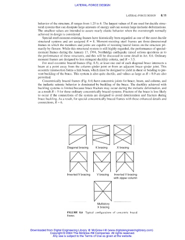
Concentrically braced frames (Fig. 8.6) have concentric joints for brace, beam, and column, and
the inelastic seismic behavior is dominated by buckling of the brace. The ductility achieved with
buckling systems is limited because brace fracture may occur during the inelastic deformation, and
as a result R = 5 for these ordinary concentrically braced systems. Fracture of the brace is less likely
to occur if the connections of the system are designed to avoid deterioration and fracture during
brace buckling. As a result, for special concentrically braced frames with these enhanced details and
connections, R = 6.
Diagonal bracing K bracing X bracing
Inverted V bracing V bracing Inverted V bracing
with zipper column
Multistory
X bracing
FIGURE 8.6 Typical configurations of concentric braced
frames.
Downloaded from Digital Engineering Library @ McGraw-Hill (www.digitalengineeringlibrary.com)
Copyright © 2004 The McGraw-Hill Companies. All rights reserved.
Any use is subject to the Terms of Use as given at the website.