
Page 157 - Structural Steel Designers Handbook AISC, AASHTO, AISI, ASTM, and ASCE-07 Design Standards
P. 157
Brockenbrough_Ch03.qxd 9/29/05 5:05 PM Page 3.89
CONNECTIONS
CONNECTIONS 3.89
Though it does not affect connection design, if desired, the internal moment in the column can be
calculated as
(3.74)
M c−internal = M c − M c−interface
Example of Bracing Connection. Consider the connection shown in Fig. 3.50. The member on the
right of the joint is a “collector” that adds load to the bracing truss. The design in this example is for
seismic loads. The brace consists of a pair of MC12 × 45 with toes 1.5 in apart. The trial gusset
thickness is thus chosen to be 1.5 in. The completed design is shown in Fig. 3.50. In this case,
because of the high specified beam shear of 170 kips, it is proposed to use a special case of the uni-
form force method that sets the vertical component of the load between the gusset and the beam, V b ,
to zero. Figure 3.50 shows the resultant force distribution. This method is called Special Case 2 of
the uniform force method and is discussed in detail elsewhere (AISC, 1992: AISC, 1994).
Brace-to-Gusset Connection
WELD. The brace is field welded to the gusset with fillet welds. Because of architectural constraints,
the gusset size is to be kept to 30 in horizontally and 24.5 in vertically. From the geometry of the
1
gusset and brace, about 17 in of fillet weld can be accommodated. The weld size in / 16ths is
D = 855 = 903.
4 ×17 ×1 392.
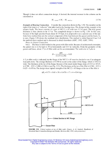
A / 8-in fillet weld is indicated, but the flange of the MC12 × 45 must be checked to see if an adequate
5
load path exists. The average thickness of 0.700 in occurs at the center of the flange, which is 4.012 in
2
wide. The thickness at the toe of the flange, because of the usual inside flange slope of 2/12 or 16 / 3%,
is 0.700 − 2/12 × 2.006 = 0.366 in (see Fig. 3.51). The thickness at the toe of the fillet is 0.366 + 2/12 ×
0.625 = 0.470 in. The design shear rupture strength of the MC12 × 45 flange at the toe of the fillet is
φR t = 0.75 × 0.60 × 58 × 0.470 × 17 × 4 = 834 kips
FIGURE 3.51 Critical section at toe of fillet weld. (Source: A. R. Tamboli, Handbook of
Structural Steel Connection Design and Details, McGraw-Hill, 1999, with permission.)
Downloaded from Digital Engineering Library @ McGraw-Hill (www.digitalengineeringlibrary.com)
Copyright © 2004 The McGraw-Hill Companies. All rights reserved.
Any use is subject to the Terms of Use as given at the website.