Page 162 - Structural Steel Designers Handbook AISC, AASHTO, AISI, ASTM, and ASCE-07 Design Standards
P. 162

Brockenbrough_Ch03.qxd  9/29/05  5:05 PM  Page 3.94


                                                        CONNECTIONS


                   3.94  CHAPTER THREE

                                 Prying action is now checked using the method and notation of the AISC Manual:
                                                                .
                                                                        =
                                                        b =  55 .  − 047  − 0 375 2 14 in
                                                                          .
                                                                    .
                                                              2
                                                            + 47 5 5
                                                        a =  80 .  −  .  = 149 in
                                                                       .
                                                               2
                               Check 1.25b = 1.25 × 2.14 = 2.68 in. Since 2.68 > 1.49, use a = 1.49 in.
                                                              .
                                                     b ′ = 214.  −  10  = 164 in
                                                                  .
                                                              2
                                                         .
                                                     a ′ = 149 +  10 .  = 199
                                                                  .
                                                              2
                                                      ρ  = 0 824
                                                         .
                                                            .
                                                      δ  =−  125  = 0 583
                                                                 .
                                                        1
                                                            3
                                                                    .
                                                           .
                                                     t c  =  444 × 291 .  ×164  = 110 in
                                                                         .
                                                               ×
                                                              358
                                                                     .
                                                     α ′ =   1        010   2  −  1   = 108
                                                                               .
                                                         0 583 ×1 824    075   
                                                         .
                                                               .
                                                                     .
                                                                   The design strength per bolt, including prying, is
                                                                               075.    2
                                                                        T = 29 1     1 (  + 0 583.  ×1 00.  )
                                                                             .
                                                                        d
                                                                               110.  
                                                                          = 21 4.  kips > 15 7 kips  OK
                                                                                     .
                                                                   In addition to the prying check, the clips should
                                                                 also be checked for gross and net shear, but these will
                                                                 not control in this case.
                                                                   WELD OF CLIPS TO BEAM WEB.  The weld is a C-
                                                                 shaped weld with length l = 21 in, kl = 3.5 in, k =
                                                                 3.5/21 = 0.167. From the AISC Manual, Table 8-9,
                                                                 xl = 0.0220 × 21 = 0.462 in, so al = 6 − 0.462 = 5.538
                                                                 in, and a = 5.538/21 = 0.264. Since tan 220/170 =
                                                                                              −1
                                                                 52.3°, use the chart for 45°. By interpolation, C = 2.56.
                                                                 A  / 4-in fillet weld has a capacity of φR w = 0.75 × 2.56 ×
                                                                   1
                                                                 4 × 2 × 21 = 323 kips. To support this weld, the web
                                                                 thickness required is 0.90 × 0.60 × 50 × t w > 1.392 ×
                                                                 4 × 2. Thus, t w required ≥ 0.41 in. Since the actual
                                                                 web thickness is 0.470 in, the weld is fully effective
                                                                 and has the calculated capacity. Thus, since 323 kips >
                                                                  220 + 170 2  = 278 kips, the  / 4-in fillet weld is OK.
                                                                                       1
                                                                     2
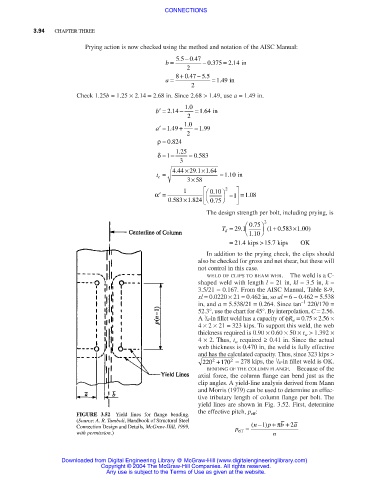
                                                                   BENDING OF THE COLUMN FLANGE. Because of the
                                                                 axial force, the column flange can bend just as the
                                                                 clip angles. A yield-line analysis derived from Mann
                                                                 and Morris (1979) can be used to determine an effec-
                                                                 tive tributary length of column flange per bolt. The
                                                                 yield lines are shown in Fig. 3.52. First, determine
                                                                 the effective pitch, p eff :
                               FIGURE 3.52  Yield lines for flange bending.
                               (Source: A. R. Tamboli, Handbook of Structural Steel  p + π
                                                                                   1
                               Connection Design and Details, McGraw-Hill, 1999,  p  =  ( n − )  b + 2 a
                               with permission.)                            eff       n
                           Downloaded from Digital Engineering Library @ McGraw-Hill (www.digitalengineeringlibrary.com)
                                      Copyright © 2004 The McGraw-Hill Companies. All rights reserved.
                                       Any use is subject to the Terms of Use as given at the website.
   157   158   159   160   161   162   163   164   165   166   167