
Page 282 - Structural Steel Designers Handbook AISC, AASHTO, AISI, ASTM, and ASCE-07 Design Standards
P. 282
Brockenbrough_Ch06.qxd 9/29/05 5:15 PM Page 6.4
DESIGN OF BUILDING MEMBERS
6.4 CHAPTER SIX
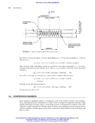
FIGURE 6.1 Detail of a splice in the bottom chord of a truss.
2
Try a W14 × 176 section with A g = 51.8 in , flange thickness t f = 1.31 in, and web thickness t w = 0.83 in.
The net area is
A n = 51.8 − (2 × 1.31 × 1.4375 × 2 + 2 × 0.83 × 1.4375) = 41.88 in 2
Since all parts of the wide-flange section are connected at the splice connection, U = 1 for deter-
2
mination of the effective area from Eq. (6.5). Thus A e = A n = 41.88 in . From Eq. (6.3b), the design
strength is
φP n = 0.75 × 65 × 41.88 = 2042 kips < 2280 kips NG
2
Try a W14 × 193 with A g = 56.8 in , t f = 1.44 in, and t w = 0.89 in. The net area is
A n = 56.8 − (2 × 1.44 × 1.4375 × 2 + 2 × 0.89 × 1.4375)
= 45.96 in 2
From Eq. (6.3b), the design strength is
φP n = 0.75 × 65 × 45.96 = 2241 kips < 2280 ksi NG
Use the next size, W14 × 211.
6.4 COMPRESSION MEMBERS
Steel members in buildings subject to compressive axial loads include columns, truss members,
struts, and diagonal braces. Slenderness is a major factor in design of compression members. Most
suitable steel shapes are pipes, tubes, or wide-flange sections, as designated for columns in the AISC
“Manual of Steel Construction.” Double angles, however, are commonly used for diagonal braces
and truss members. Double angles can be easily connected to other members with gusset plates and
bolts or welds.
Downloaded from Digital Engineering Library @ McGraw-Hill (www.digitalengineeringlibrary.com)
Copyright © 2004 The McGraw-Hill Companies. All rights reserved.
Any use is subject to the Terms of Use as given at the website.