
Page 285 - Structural Steel Designers Handbook AISC, AASHTO, AISI, ASTM, and ASCE-07 Design Standards
P. 285
Brockenbrough_Ch06.qxd 9/29/05 5:15 PM Page 6.7
DESIGN OF BUILDING MEMBERS
DESIGN OF BUILDING MEMBERS 6.7
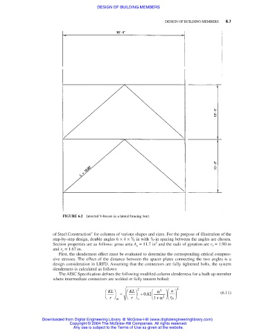
FIGURE 6.2 Inverted V-braces in a lateral bracing bent.
of Steel Construction” for columns of various shapes and sizes. For the purpose of illustration of the
3
5
step-by-step design, double angles 6 × 4 × / 8 in with / 8-in spacing between the angles are chosen.
2
Section properties are as follows: gross area A g = 11.7 in and the radii of gyration are r x = 1.90 in
and r y = 1.67 in.
First, the slenderness effect must be evaluated to determine the corresponding critical compres-
sive stresses. The effect of the distance between the spacer plates connecting the two angles is a
design consideration in LRFD. Assuming that the connectors are fully tightened bolts, the system
slenderness is calculated as follows:
The AISC Specification defines the following modified column slenderness for a built-up member
where intermediate connectors are welded or fully tension bolted:
KL = KL 2 α 2 a 2 (6.11)
r m r o + 082. 1 + α 2 r ib
Downloaded from Digital Engineering Library @ McGraw-Hill (www.digitalengineeringlibrary.com)
Copyright © 2004 The McGraw-Hill Companies. All rights reserved.
Any use is subject to the Terms of Use as given at the website.