Page 291 - Structural Steel Designers Handbook AISC, AASHTO, AISI, ASTM, and ASCE-07 Design Standards
P. 291

Brockenbrough_Ch06.qxd  9/29/05  5:15 PM  Page 6.13


                                                    DESIGN OF BUILDING MEMBERS


                                                                              DESIGN OF BUILDING MEMBERS  6.13

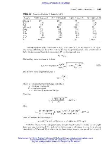
                                  TABLE 6.2 Properties of Selected W Shapes for LRFD
                                   Property  W18 × 35 Grade 50  W18 × 40 Grade 50  W21 × 50 Grade 50  W21 × 62 Grade 50
                                  ϕM p , kip⋅ft  249              294             416             540
                                  L p , ft        4.31             4.49            4.59            6.25
                                  L r , ft        11.5            12.0            12.5             16.7
                                  ϕM r , kip⋅ft  173              205             285             381
                                  S x , in 3      57.6            68.4            94.5            127
                                  l y , in 4      15.3            19.1            24.9             57.5
                                  h o , in        17.28           17.38           20.28            20.39
                                  r y , in        1.22             1.27            1.30            1.77
                                  J, in 4         0.506            0.81            1.14            57.5
                                                1140             1440            2560            5970
                                  C w


                                    The next step is to find a section that if its L r is less than 20 ft, its M r exceeds 277.5 kip⋅ft.
                                  The manual table indicates that a W21 × 50 has the required properties (Table 6.2). With the aid of
                                  Table 6.2, the nominal flexural design strength M n can be computed from

                                                                  M n = F cr S x
                                  The buckling stress is defined as follows:

                                                                   C π 2 E        Jc   L  2
                                                  F =  buckling stress =  b  1 + 0 078    b         (6.22)
                                                                              .
                                                   cr
                                                                   ( Lr / ) 2    Sh   r 
                                                                                      ts
                                                                                  x o
                                                                     b ts
                                  The effective radius of gyration r tx (in) is
                                                                       IC
                                                                  r =   yw
                                                                   2
                                                                  ts
                                                                       S x
                                  where h o = distance between the flange centroids, in
                                        J = torsional constant, in 4
                                       C w = warping constant
                                        c = 1.0 for doubly symmetric I-shape
                                  Therefore,
                                                                          /
                                                              24 9 .  × 2560    12
                                                          r =            = 1 635 in
                                                                             .
                                                          tx
                                                                 94 5 .  
                                  Also,
                                                                       .
                                                          ,
                                             F =  1 0 .  × π 2  × 29 000  1 + 0 078  114 ×10 .   20 ×12   2  = 18 77  ksi
                                                                                          .
                                                                  .
                                              cr            2                        
                                                                            .
                                                                                 .
                                                 [( 20 ×12 1 635]     94 5 .  × 20 28  1 635
                                                       )/ .
                                  Thus, the nominal flexural strength is
                                                M n = 18.77 × 94.5 = 1774 kip⋅in = 147.9 kip⋅ft < 277.5 kip⋅ft
                                    The W21 × 50 does not have adequate flexural strength. Therefore, trials to find the lowest-weight
                                  larger size must be continued. This trial-and-error process can be eliminated by using beam-selector
                                  charts in the AISC manual. These charts give the beam design moment corresponding to unbraced
                              Downloaded from Digital Engineering Library @ McGraw-Hill (www.digitalengineeringlibrary.com)
                                         Copyright © 2004 The McGraw-Hill Companies. All rights reserved.
                                          Any use is subject to the Terms of Use as given at the website.
   286   287   288   289   290   291   292   293   294   295   296