
Page 295 - Structural Steel Designers Handbook AISC, AASHTO, AISI, ASTM, and ASCE-07 Design Standards
P. 295
Brockenbrough_Ch06.qxd 9/29/05 5:15 PM Page 6.17
DESIGN OF BUILDING MEMBERS
DESIGN OF BUILDING MEMBERS 6.17
where f c ′= concrete compressive strength, ksi
2
A c = area of the concrete within the effective slab width, in (if the metal deck ribs are per-
pendicular to the beam, the area consists only of the concrete above the metal deck. If,
however, the ribs are parallel to the beam, all the concrete, including the concrete in
the ribs, comprises the area.)
Equation (6.25) gives the yield strength of the steel beam:
(6.25)
C t = A s F y
where A s = area of the steel section (not applicable to hybrid sections), in 2
F y = yield stress of the steel, ksi
Equation (6.26) expresses the strength of the shear connectors:
s ∑
C = Q n (6.26)
where ∑Q n is the sum of the nominal strength of the shear connectors between the point of maxi-
mum positive moment and zero moment on either side.
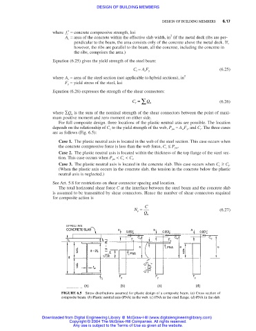
For full composite design. three locations of the plastic neutral axis are possible. The location
depends on the relationship of C c to the yield strength of the web, P yw = A w F y , and C t . The three cases
are as follows (Fig. 6.5):
Case 1. The plastic neutral axis is located in the web of the steel section. This case occurs when
the concrete compressive force is less than the web force, C c ≤ P yw .
Case 2. The plastic neutral axis is located within the thickness of the top flange of the steel sec-
tion. This case occurs when P yw < C c < C t .
Case 3. The plastic neutral axis is located in the concrete slab. This case occurs when C c ≥ C t .
(When the plastic axis occurs in the concrete slab, the tension in the concrete below the plastic
neutral axis is neglected.)
See Art. 5.8 for restrictions on shear connector spacing and location.
The total horizontal shear force C at the interface between the steel beam and the concrete slab
is assumed to be transmitted by shear connectors. Hence the number of shear connectors required
for composite action is
N = C (6.27)
s
Q n
FIGURE 6.5 Stress distributions assumed for plastic design of a composite beam. (a) Cross section of
composite beam. (b) Plastic neutral axis (PNA) in the web. (c) PNA in the steel flange. (d) PNA in the slab.
Downloaded from Digital Engineering Library @ McGraw-Hill (www.digitalengineeringlibrary.com)
Copyright © 2004 The McGraw-Hill Companies. All rights reserved.
Any use is subject to the Terms of Use as given at the website.