
Page 297 - Structural Steel Designers Handbook AISC, AASHTO, AISI, ASTM, and ASCE-07 Design Standards
P. 297
Brockenbrough_Ch06.qxd 9/29/05 5:15 PM Page 6.19
DESIGN OF BUILDING MEMBERS
DESIGN OF BUILDING MEMBERS 6.19
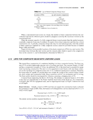
TABLE 6.3 Q n for Partial Composite Design (kips)
Location of PNA Q n and concrete compression
(1) A x F y
(2)–(5) A s F y –2∆A f F* y
(6) 0.5[C(5) + C(7)] †
(7) 0.25A s F y
*∆A f = area of the segment of the steel flange above the plastic
neutral axis (PNA).
† C(n) = compressive force at location (n).
When a concentrated load occurs on a beam, the number of shear connectors between the con-
centrated load and the inflection point should be adequate to develop the maximum moment at the
concentrated load.
When the moment capacity of a fully composite beam is much greater than the applied moment,
a partially composite beam may be utilized. It requires fewer shear connectors and thus has a lower
construction cost. A partially composite design also may be used advantageously when the number
of shear connectors required for a fully composite section cannot be provided because of limited
flange width and length.
Figure 6.6 shows seven possible locations of the plastic neutral axis (PNA) in a steel section. The
horizontal shear between the steel section and the concrete slab, which is equal to the compressive
force in the concrete C, can be determined as illustrated in Table 6.3.
6.13 LRFD FOR COMPOSITE BEAM WITH UNIFORM LOADS
The typical floor construction of a multistory building is to have composite framing. The floor con-
1
sists of 3 / 4-in-thick lightweight concrete over a 2-in-deep steel deck. The concrete weighs 115 lb/ft 3
and has a compressive strength of 3.0 ksi. An additional 30% of the dead load is assumed for equip-
ment load during construction. The deck is to be supported on steel beams with stud shear connec-
tors on the top flange for composite action (Art. 6.12). Unshored construction is assumed. Therefore,
the beams must be capable of carrying their own weight, the weight of the concrete before it hard-
1
3
ens, deck weight, and construction loads. Shear connectors will be / 4 in in diameter and 3 / 2 in long.
The floor system should be investigated for vibration, assuming a damping ratio of 5%.
A typical beam supporting the deck is 30 ft long. The distance to adjacent beams is 10 ft. Ribs
of the deck are perpendicular to the beam. Uniform dead loads on the beam are, for construction,
0.50 kip/ft, plus 30% for equipment loads, and for superimposed load, 0.25 kip/ft. Uniform live load
is 0.50 kip/ft.
Beam Selection. Initially, a beam of A992 steel that can support the construction loads is selected.
It is assumed to weigh 22 lb/ft. Thus, the beam is to be designed for a service dead load of 0.5 × 1.3 +
0.022 = 0.672 kip/ft.
Factored load = 0.672 × 1.4 = 0.941 kip/ft
Factored moment = M u = 0.941 × 30 2 = 105.8 kip⋅ft
8
The plastic section modulus required therefore is
Z = M u = 105 8 . ×12 = 28 2 . in 3
φ F y 09 . × 50
4
3
Use a W14 × 22 (Z = 33.2 in and moment of inertia I = 199 in ).
Downloaded from Digital Engineering Library @ McGraw-Hill (www.digitalengineeringlibrary.com)
Copyright © 2004 The McGraw-Hill Companies. All rights reserved.
Any use is subject to the Terms of Use as given at the website.