
Page 296 - Structural Steel Designers Handbook AISC, AASHTO, AISI, ASTM, and ASCE-07 Design Standards
P. 296
Brockenbrough_Ch06.qxd 9/29/05 5:15 PM Page 6.18
DESIGN OF BUILDING MEMBERS
6.18 CHAPTER SIX
where Q n = nominal strength of one shear connector, kips
N s = number of shear studs between maximum positive moment and zero moment on each
side of the maximum positive moment
The nominal strength of a shear stud connector embedded in a solid concrete slab may be com-
puted from
Q = 05 A sc f E ′ c c ≤ R R A F u (6.28)
.
p sc
g
n
where A sc = cross-sectional area of stud, in 2
f c ′= specified compressive strength of concrete, ksi
E c = modulus of elasticity of the concrete, ksi
.
= w 15 f ′ c
w = unit weight of the concrete, lb/ft 3
F u = specified minimum tensile strength of a stud, ksi
R g and R p are strength reduction factors, Art. 5.8.6.
For a beam with nonsymmetrical loading, the distances between the maximum positive moment and
point of zero moment (inflection point) on either side of the point of maximum moment will not be
equal. Or if one end of a beam has negative moment, then the inflection point will not be at that end.
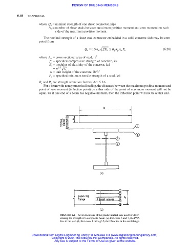
FIGURE 6.6 Seven locations of the plastic neutral axis used for deter-
mining the strength of a composite beam. (a) For cases 6 and 7, the PNA
lies in the web. (b) For cases 1 through 5, the PNA lies in the steel flange.
Downloaded from Digital Engineering Library @ McGraw-Hill (www.digitalengineeringlibrary.com)
Copyright © 2004 The McGraw-Hill Companies. All rights reserved.
Any use is subject to the Terms of Use as given at the website.