
Page 323 - Structural Steel Designers Handbook AISC, AASHTO, AISI, ASTM, and ASCE-07 Design Standards
P. 323
Brockenbrough_Ch07.qxd 9/29/05 5:16 PM Page 7.7
FLOOR AND ROOF SYSTEMS
FLOOR AND ROOF SYSTEMS 7.7
Attachment of adjacent deck units to each other, that is, sidelap connection, can be made with
welds, screws, or button punches. Generally, the maximum spacing of sidelap attachments is 36 in.
In addition to diaphragm or other loading requirements, the type, size, and spacing of attachments is
sometimes dictated by insurance (Factory Mutual or Underwriters’ Laboratories) requirements.
1
3
Weld sizes generally range between / 2-in and / 4-in minimum visible diameter. When metal deck
is welded to steel framing, welding washers should be used if the deck thickness is less than 22 ga
to minimize the possibility of burning through the deck. Sidelap welding is not recommended for
deck thicknesses of 22 ga and thinner.
Screws can be either self-drilling or self-tapping. Self-drilling screws have drill points and
threads formed at the screw end. This enables direct installation without the need for predrilling of
holes in the steel framing or metal deck. Self-tapping screws require that a hole be drilled prior to
installation. Typical screw sizes are No. 12 and No. 14 (with 0.216-in and 0.242-in shank diameter,
respectively) for attachment of metal deck to steel framing. No. 8 and No. 10 screws (with 0.164-in
and 0.190-in shank diameter, respectively) are frequently used for sidelap connections.
Powder-driven fasteners are installed through the metal deck into the steel framing with pneu-
matic or powder-actuated equipment. Predrilled holes are not required. These types of fasteners are
not used for sidelap connections.
Button punches can be used for sidelap connections of certain types of metal deck that utilize
upstanding seams at the sidelaps. However, since uniformity of installation is difficult to control, but-
ton punches are not usually considered to contribute significantly to diaphragm strength.
The diaphragm capacity of various types and arrangements of metal deck and attachments is
given in the Steel Deck Institute Diaphragm Design Manual.
7.2 PRECAST-CONCRETE PLANK
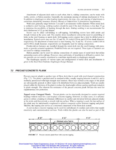
Precast-concrete plank is another type of floor deck that is used with steel-framed construction
(Fig. 7.7). The plank is prefabricated in standard widths, usually ranging between 4 and 8 ft, and is
normally prestressed with high-strength steel tendons. Shear keys formed at the edges of the plank
are subsequently grouted, to allow loads to be distributed between adjacent planks. Voids are usually
placed within the thickness of the plank to reduce the deadweight without causing significant reduction
in plank strength. The inherent fire resistance of the precast concrete plank obviates the need for
supplementary fire protection.
Topped versus Untopped Planks. Precast planks can be structurally designed to sustain required
loadings without need for a cast-in-place concrete topping. However, in many cases, it is advanta-
geous to utilize a topping to eliminate differences in camber and elevation between adjacent planks
at the joints and thus provide a smooth slab top surface. When a topping is used, the top surface of
the plank may be intentionally roughened to achieve composite action between topping and plank.
Thereby, the topping also serves as a structural component of the floor-deck system.
A cast-in-place concrete topping can be used for embedment of conduits and outlets that supply
electricity and communication services. Voids within the planks can also be used as part of the
FIGURE 7.7 Precast-concrete plank floor with concrete topping.
Downloaded from Digital Engineering Library @ McGraw-Hill (www.digitalengineeringlibrary.com)
Copyright © 2004 The McGraw-Hill Companies. All rights reserved.
Any use is subject to the Terms of Use as given at the website.