
Page 225 - Sustainable On-Site CHP Systems Design, Construction, and Operations
P. 225
198 De s i g n
N
φ
Cogeneration tie bus
(1)
52 Utility main PT 77
A
43
CT
50
3 51 67 43 V 81
F
77
(2)
PT 43
27 81 47
25
Medium voltage
2.4 to 15 kV
To generator
59 R connection
To utility
service
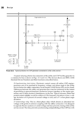
FIGURE 11-1 Typical protection for CHP generator connected to utility–utility section.
A typical relaying scheme for connection of the utility and CHP facility generator to
a common tie bus is shown in Figs. 11-1 and 11-2. The devices shown are IEEE/ANSI
Standard Device Numbers and their function is described below.
25-Synchronizing check device. Electronic control causes all online CHP engine–
generator sets to be matched in frequency, voltage, and phase angle to the utility
service before the utility connection circuit breaker (ANSI device #52) can be closed.
Differences between the utility and generator bus must be minimized at the instant
of paralleling to prevent transient mechanical torque impulses on the engine gen-
erators and to limit electrical disturbances on the bus. Typical tolerance limits that
permit control stability would be within a 0.2 Hz frequency deviation or less; a volt-
age deviation of 10 percent of normal voltage or less; and a 5° or less phase angle
deviation.
27-Undervoltage relay. This is a three-phase relay which detects an abnormal low
voltage at the point of common coupling with the utility connection. It is designed
to separate the two systems on undervoltage and also prevents closing of the utility
service circuit. The relay prevents synchronizing and paralleling of the CHP bus with