
Page 31 - Sustainable On-Site CHP Systems Design, Construction, and Operations
P. 31
10 CHP B a s i c s
with the best return on investment (ROI) and/or outcome typically requires a critical
analysis of probable operating scenarios, which rely heavily upon historical operating
information along with facility current and foreseeable needs.
Use of CHP is generally more attractive within larger buildings with multiple use
occupancies and/or longer daily operating hours and particularly in urban areas where
high electrical and somewhat lower gas rates prevail. CHP is also more common where
utilization of available waste heat for cooling production can minimize peak electrical
demand by offsetting electric-drive chiller operation.
Where greater availability and selection among low-cost microturbines exist, inter-
est in both co- and trigeneration is increasing. Additionally, where opportunities for
larger combined (i.e., hybrid) operations exist, both co- and trigeneration are provided
with further incentives. Such opportunities have created greater owner interest. Yet
until recently, CHP applications were often overlooked by facility owners. Of course,
challenges sometimes arise with noise reduction, available gas pressure at the site,
particularly for CTGs, and lack of staff experience. Combined gas and electrical utili-
ties tend to be more flexible, particularly when CHP facilities are intended to operate
in parallel with the serving utility. Sometimes, excessive utility interconnect require-
ments or owner disappointment with income streams can serve as a barrier to CHP
implementation.
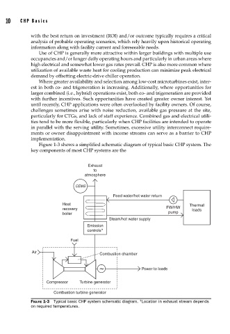
Figure 1-3 shows a simplified schematic diagram of typical basic CHP system. The
key components of most CHP systems are the
Exhaust
to
atmosphere
CEMS
Feed water/hot water return
Heat Thermal
recovery FW/HW loads
boiler pump
Steam/hot water supply
Emission
controls ∗
Fuel
Air
Combustion chamber
~ Power to loads
Compressor Turbine generator
Combustion turbine generator
FIGURE 1-3 Typical basic CHP system schematic diagram. ∗ Location in exhaust stream depends
on required temperatures.