
Page 67 - Synthetic Fuels Handbook
P. 67
NATURAL GAS 55
such as methane, ethane, nitrogen, and hydrogen. During the past 15 years, more than
50 systems have been installed in the chemical process industry worldwide. The main
applications are nitrogen removal and recovery of natural gas liquids (Lokhandwala, 2000;
Hall and Lokhandwala, 2004).
2.7.6 Sulfur Recovery Processes
The side stream from acid gas treating units consists mainly of hydrogen sulfide and/or
carbon dioxide. Carbon dioxide is usually vented to the atmosphere but sometimes is
recovered for carbon dioxide floods. Hydrogen sulfide could be routed to an incinerator or
flare, which would convert the hydrogen sulfide to sulfur dioxide. The release of hydrogen
sulfide to the atmosphere may be limited by environmental regulations. There are many
specific restrictions on these limits, and the allowable limits are revised periodically. In any
case, environmental regulations severely restrict the amount of hydrogen sulfide that can
be vented or flared in the regeneration cycle.
Most sulfur recovery processes use chemical reactions to oxidize hydrogen sulfide and
produce elemental sulfur. These processes are generally based either on the reaction of
hydrogen sulfide and oxygen or hydrogen sulfide and sulfur dioxide. Both reactions yield
water and elemental sulfur. These processes are licensed and involve specialized catalysts
and/or solvents. These processes can be used directly on the produced gas stream. Where
large flow rates are encountered, it is more common to contact the produced gas stream
with a chemical or physical solvent and use a direct conversion process on the acid gas
liberated in the regeneration step.
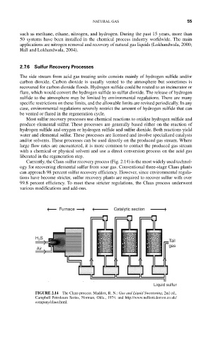
Currently, the Claus sulfur recovery process (Fig. 2.14) is the most widely used technol-
ogy for recovering elemental sulfur from sour gas. Conventional three-stage Claus plants
can approach 98 percent sulfur recovery efficiency. However, since environmental regula-
tions have become stricter, sulfur recovery plants are required to recover sulfur with over
99.8 percent efficiency. To meet these stricter regulations, the Claus process underwent
various modifications and add-ons.
Furnace Catalytic section
H 2 S
Tail
gas
Air
Liquid sulfur
FIGURE 2.14 The Claus process. Maddox, R. N.: Gas and Liquid Sweetening, 2nd ed.,
Campbell Petroleum Series, Norman, Okla., 1974. and http://www.nelliott.demon.co.uk/
company/claus.html.