
Page 229 -
P. 229
196 Part 3 • the analysis Process
Figure 7.16
y
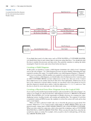
A context-level data flow diagram Back-Ordered Item Inventory
Control
for the order processing system at Department
World’s Trend.
0
Customer Order Shipped Order
New Customer Information Order Customer Billing Statement
Customer Processing Customer
Item Number of Description System Item Information
Order Picking List
Accounting Accounts Receivable Report Order Goods Warehouse
Department
If you think there need to be data stores such as ITEM MASTER or CUSTOMER MASTER,
you should draw those in and connect them to processes using data flows. You should also take
the time to number the processes and data stores. Pay particular attention to making the labels
meaningful. Check for errors and correct them before moving on.
Creating a Child Diagram
At this point, you should try to draw a child diagram (sometimes also called a level 1 diagram)
such as the one in Figure 7.18. Child diagram processes are more detailed, illustrating the logic
required to produce the output. You should number your child diagrams Diagram 1, Diagram 2,
and so on, in accordance with the number you assigned to each process in the level 0 diagram.
When you draw a child diagram, you should make a list of subprocesses first. A process such
as ADD CUSTOMER ORDER can have subprocesses (in this case, there are seven). Connect
these subprocesses to one another and also to data stores when appropriate. Subprocesses do not
have to be connected to external entities, because we can always refer to the parent (or level 0)
data flow diagram to identify these entities. Label the subprocesses 1.1, 1.2, 1.3, and so on. Take
the time to check for errors and make sure the labels make sense.
Creating a Physical Data Flow Diagram from the Logical DFD
If you want to go beyond the logical model and draw a physical model as well, look at Figure 7.19,
which is an example of a physical data flow child diagram of process 3, PRODUCE PICKING
SLIPS. Physical DFDs give you the opportunity to identify processes for scanning bar codes,
displaying screens, locating records, and creating and updating files. The sequence of activities
is important in physical DFDs because the emphasis is on how the system will work and in what
order events happen.
When you label a physical model, take care to describe the process in great detail. For
example, Subprocess 3.3 in a logical model could simply be SORT ORDER ITEM, but in the
physical model, a better label is SORT ORDER ITEM BY LOCATION WITHIN CUSTOMER.
When you write a label for a data store, refer to the actual file or database, such as CUSTOMER
MASTER FILE or SORTED ORDER ITEM FILE. When you describe data flows, describe the
actual form, report, or screen. For example, when you print a slip for order picking, call the data
flow ORDER PICKING SLIP.