
Page 294 -
P. 294
chaPter 10 • object-oriented systems analysis and design Using Uml 261
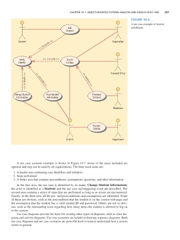
Figure 10.6
A use case example of student
Add enrollment.
Student
<< include >>
Student Registration
Verify << include >> Enroll
Identity in Class
<< include >> << include >> << extend >> Financial Office
Change Student View Student Purchase
Information Information Textbook
Bookstore
Transfer
Credits
Student Department
A use case scenario example is shown in Figure 10.7. Some of the areas included are
optional and may not be used by all organizations. The three main areas are:
1. A header area containing case identifiers and initiators
2. Steps performed
3. A footer area that contains preconditions, assumptions, questions, and other information
In the first area, the use case is identified by its name, Change Student Information;
the actor is identified as a Student; and the use case and triggering event are described. The
second area contains a series of steps that are performed as long as no errors are encountered.
Finally, in the third area, all the pre- and postconditions and assumptions are identified. Some
of these are obvious, such as the precondition that the student is on the correct web page and
the assumption that the student has a valid student ID and password. Others are not so obvi-
ous, such as the outstanding issue regarding how many times the student is allowed to log on
to the system.
Use case diagrams provide the basis for creating other types of diagrams, such as class dia-
grams and activity diagrams. Use case scenarios are helpful in drawing sequence diagrams. Both
use case diagrams and use case scenarios are powerful tools to help us understand how a system
works in general.