
Page 296 -
P. 296
chaPter 10 • object-oriented systems analysis and design Using Uml 263
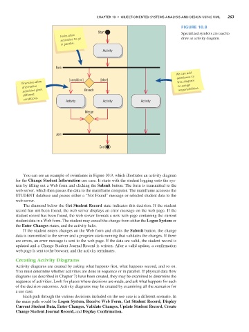
Figure 10.8
Start Specialized symbols are used to
Forks allow
activities to go draw an activity diagram.
in parallel.
Activity
Fork
We can add
swimlanes to
Branches allow [condition] [else] this diagram
alternative to assign
activities given Branch responsibilities.
different
conditions. Activity Activity Activity
Merge
Join
End
You can see an example of swimlanes in Figure 10.9, which illustrates an activity diagram
for the Change Student Information use case. It starts with the student logging onto the sys-
tem by filling out a Web form and clicking the Submit button. The form is transmitted to the
web server, which then passes the data to the mainframe computer. The mainframe accesses the
STUDENT database and passes either a “Not Found” message or selected student data to the
web server.
The diamond below the Get Student Record state indicates this decision. If the student
record has not been found, the web server displays an error message on the web page. If the
student record has been found, the web server formats a new web page containing the current
student data in a Web form. The student may cancel the change from either the Logon System or
the Enter Changes states, and the activity halts.
If the student enters changes on the Web form and clicks the Submit button, the change
data is transmitted to the server and a program starts running that validates the changes. If there
are errors, an error message is sent to the web page. If the data are valid, the student record is
updated and a Change Student Journal Record is written. After a valid update, a confirmation
web page is sent to the browser, and the activity terminates.
Creating Activity Diagrams
Activity diagrams are created by asking what happens first, what happens second, and so on.
You must determine whether activities are done in sequence or in parallel. If physical data flow
diagrams (as described in Chapter 7) have been created, they may be examined to determine the
sequence of activities. Look for places where decisions are made, and ask what happens for each
of the decision outcomes. Activity diagrams may be created by examining all the scenarios for
a use case.
Each path through the various decisions included on the use case is a different scenario. In
the main path would be Logon System, Receive Web Form, Get Student Record, Display
Current Student Data, Enter Changes, Validate Changes, Update Student Record, Create
Change Student Journal Record, and Display Confirmation.