
Page 301 -
P. 301
268 Part 3 • the analysis Process
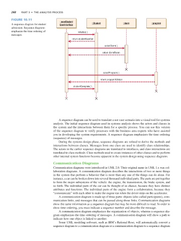
Figure 10.11
::newStudent
A sequence diagram for student UserInterface ::Student ::dorm ::program
admission. Sequence diagrams
emphasize the time ordering of initialize( )
messages.
return studentNumber
selectDorm( )
return dormRoom
selectProgram( )
return programAdvisor
studentComplete( )
A sequence diagram can be used to translate a use case scenario into a visual tool for systems
analysis. The initial sequence diagram used in systems analysis shows the actors and classes in
the system and the interactions between them for a specific process. You can use this version
of the sequence diagram to verify processes with the business area experts who have assisted
you in developing the system requirements. A sequence diagram emphasizes the time ordering
(sequence) of messages.
During the systems design phase, sequence diagrams are refined to derive the methods and
interactions between classes. Messages from one class are used to identify class relationships.
The actors in the earlier sequence diagrams are translated to interfaces, and class interactions are
translated to class methods. Class methods used to create instances of other classes and to perform
other internal system functions become apparent in the system design using sequence diagrams.
Communication Diagrams
Communication diagrams were introduced in UML 2.0. Their original name in UML 1.x was col-
laboration diagrams. A communication diagram describes the interactions of two or more things
in the system that perform a behavior that is more than any one of the things can do alone. For
instance, a car can be broken down into several thousand individual parts. The parts are put together
to form the major subsystems of the vehicle: the engine, the transmission, the brake system, and
so forth. The individual parts of the car can be thought of as classes, because they have distinct
attributes and functions. The individual parts of the engine form a collaboration, because they
“communicate” with each other to make the engine run when the driver steps on the accelerator.
A communication diagram is made up of three parts: objects (also called participants), com-
munication links, and messages that can be passed along those links. Communication diagrams
show the same information as a sequence diagram but may be more difficult to read. In order to
show time ordering, you must indicate a sequence number and describe the message.
A communication diagram emphasizes the organization of objects, whereas a sequence dia-
gram emphasizes the time ordering of messages. A communication diagram will show a path to
indicate how one object is linked to another.
Some UML modeling software, such as IBM’s Rational Rose, will automatically convert a
sequence diagram to a communication diagram or a communication diagram to a sequence diagram