
Page 512 - Tandem Techniques
P. 512
Page 498
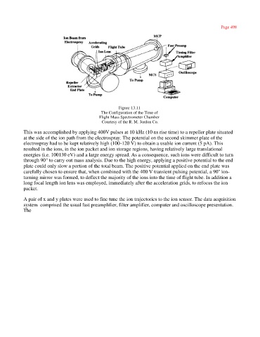
Figure 13.11
The Configuration of the Time of
Flight Mass Spectrometer Chamber
Courtesy of the R. M. Jordon Co.
This was accomplished by applying 400V pulses at 10 kHz (10 ns rise time) to a repeller plate situated
at the side of the ion path from the electrospray. The potential on the second skimmer plate of the
electrospray had to be kept relatively high (100-120 V) to obtain a usable ion current (5 pA). This
resulted in the ions, in the ion packet and ion storage regions, having relatively large translational
energies (i.e. 100130 eV) and a large energy spread. As a consequence, such ions were difficult to turn
through 90° to carry out mass analysis. Due to the high energy, applying a positive potential to the end
plate could only slow a portion of the total beam. The positive potential applied on the end plate was
carefully chosen to ensure that, when combined with the 400 V transient pulsing potential, a 90'' ion-
turning mirror was formed, to deflect the majority of the ions into the time of flight tube. In addition a
long focal length ion lens was employed, immediately after the acceleration grids, to refocus the ion
packet.
A pair of x and y plates were used to fine tune the ion trajectories to the ion sensor. The data acquisition
system comprised the usual fast preamplifier, filter amplifier, computer and oscilloscope presentation.
The