
Page 199 - The Art and Science of Analog Circuit Design
P. 199
Tripping the Light Fantastic
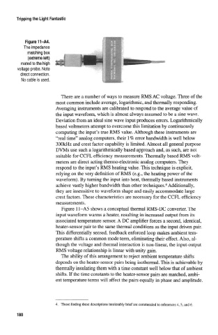
Figure 11-A4.
The impedance
matching box
(extreme toft)
mated to the high
voltage probe, Note
direct connection,
No cable is used.
There are a number of ways to measure RMS AC voltage. Three of the
most common include average, logarithmic, and thermally responding.
Averaging instruments are calibrated to respond to the average value of
the input waveform, which is almost always assumed to be a sine wave.
Deviation from an ideal sine wave input produces errors. Logarithmically
based voltmeters attempt to overcome this limitation by continuously
computing the input's true RMS value. Although these instruments are
"real time" analog computers, their 1 % error bandwidth is well below
300kHz and crest factor capability is limited. Almost all general purpose
DVMs use such a logarithmically based approach and, as such, are not
suitable for CCFL efficiency measurements. Thermally based RMS volt-
meters are direct acting thermo-electronic analog computers. They
respond to the input's RMS heating value. This technique is explicit,
relying on the very definition of RMS (e.g., the heating power of the
waveform). By turning the input into heat, thermally based instruments
4
achieve vastly higher bandwidth than other techniques. Additionally,
they are insensitive to waveform shape and easily accommodate large
crest factors. These characteristics are necessary for the CCFL efficiency
measurements.
Figure 11-A5 shows a conceptual thermal RMS-DC converter. The
input waveform warms a heater, resulting in increased output from its
associated temperature sensor. A DC amplifier forces a second, identical,
heater-sensor pair to the same thermal conditions as the input driven pair.
This differentially sensed, feedback enforced loop makes ambient tem-
perature shifts a common mode term, eliminating their effect. Also, al-
though the voltage and thermal interaction is non-linear, the input-output
RMS voltage relationship is linear with unity gain.
The ability of this arrangement to reject ambient temperature shifts
depends on the heater-sensor pairs being isothermal. This is achievable by
thermally insulating them with a time constant well below that of ambient
shifts. If the time constants to the heater-sensor pairs are matched, ambi-
ent temperature terms will affect the pairs equally in phase and amplitude.
4. Those finding these descriptions intolerably brief are commended to references 4, 5, and 6.
180