
Page 203 - The Art and Science of Analog Circuit Design
P. 203
Tripping the Light Fantastic
Appendix B
Photometric Measurements
In the final analysis the ultimate concern centers around the efficient
conversion of power supply energy to light. Emitted light varies monoto-
1
nically with power supply energy, but certainly not linearly. In particu-
lar, bulb luminosity may be highly nonlinear, particularly at high power,
vs. drive power. There are complex trade-offs involving the amount of
emitted light vs. power consumption and battery life. Evaluating these
trade-offs requires some form of photometer. The relative luminosity of
lamps may be evaluated by placing the lamp in a light tight tube and
sampling its output with photodiodes. The photodiodes are placed along
the lamp's length and their outputs electrically summed. This sampling
technique is an uncalibrated measurement, providing relative data only. It
is, however, quite useful in determining relative bulb emittance under
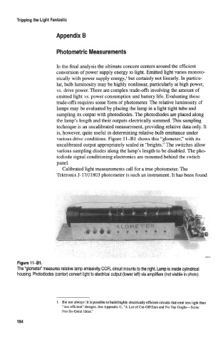
various drive conditions. Figure 11-B1 shows this "glometer," with its
uncalibrated output appropriately scaled in "brights." The switches allow
various sampling diodes along the lamp's length to be disabled. The pho-
todiode signal conditioning electronics are mounted behind the switch
panel.
Calibrated light measurements call for a true photometer. The
Tektronix J-17/J1803 photometer is such an instrument. It has been found
Figure 11-B1.
The "glometer" measures relative lamp emissivity. CCFL circuit mounts to the right. Lamp is insicte cylincfrteal
housing. Photodiodes (center) convert light to electrical output (lower left) via amplifiers (not visible in photo).
1. But not always! It is possible to build highly electrically efficient circuits that emit less light than
"less efficient" designs. See Appendix C, "A Lot of Cut-Off Ears and No Van Goghs—Some
Not-So-Great Ideas."
184