
Page 200 - The Art and Science of Analog Circuit Design
P. 200
Jim Williams
DC AMPLIFIER
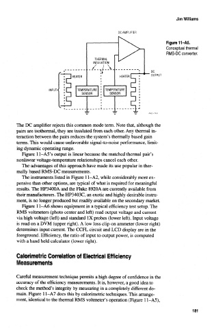
Figure tt-AS.
Conceptual thermal
RMS-DC converter.
DC
OUTPUT
INPUTX
The DC amplifier rejects this common mode term. Note that, although the
pairs are isothermal, they are insulated from each other. Any thermal in-
teraction between the pairs reduces the system's thermally based gain
terms. This would cause unfavorable signal-to-noise performance, limit-
ing dynamic operating range.
Figure 1 l-A5's output is linear because the matched thermal pair's
nonlinear voltage-temperature relationships cancel each other.
The advantages of this approach have made its use popular in ther-
mally based RMS-DC measurements.
The instruments listed in Figure 11-A2, while considerably more ex-
pensive than other options, are typical of what is required for meaningful
results. The HP3400A and the Fluke 8920A are currently available from
their manufacturers. The HP3403C, an exotic and highly desirable instru-
ment, is no longer produced but readily available on the secondary market.
Figure 1 1-A6 shows equipment in a typical efficiency test setup. The
RMS voltmeters (photo center and left) read output voltage and current
via high voltage (left) and standard IX probes (lower left). Input voltage
is read on a DVM (upper right). A low loss clip-on ammeter (lower right)
determines input current. The CCFL circuit and LCD display are in the
foreground. Efficiency, the ratio of input to output power, is computed
with a hand held calculator (lower right).
Calorimetric Correlation of Electrical Efficiency
Measurements
Careful measurement technique permits a high degree of confidence in the
accuracy of the efficiency measurements. It is, however, a good idea to
check the method's integrity by measuring in a completely different do-
main, Figure 1 1-A7 does this by calorimetric techniques. This arrange-
ment, identical to the thermal RMS voltmeter's operation (Figure 1 1-A5),
181