
Page 190 - The Combined Finite-Discrete Element Method
P. 190
CONSTANT STRAIN TETRAHEDRON FINITE ELEMENT 173
while the Green–St. Venant strain tensor due to volume changing stretch is given by
1 1 $ %
(| det F|) 2/3 − 1
T
˜
E s = (V s V − I) = I(| det F|) 2/3 − I = I (4.219)
s
2 2 2
From the strain tensors, the Cauchy stress is calculated using the constitutive law. Different
constitutive laws can be employed at this point. For instance, a constitutive law for
homogeneous isotropic material derived by analogy with the Hooks constitutive law is
given by
E 1
˜
T = E d + (4.220)
(1 + ν) (| det F|) 2/3
E 1 2µ
˜
E s + D
(1 − 2ν) (| det F|) 2/3 (| det F|) 2/3
The last component is the viscous stress, which is responsible for most of the material
damping due to deformation.
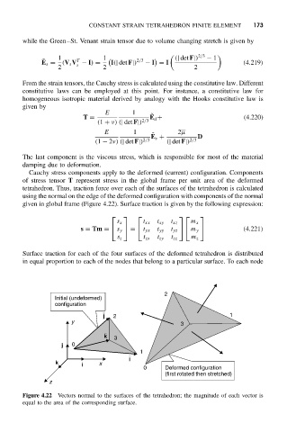
Cauchy stress components apply to the deformed (current) configuration. Components
of stress tensor T represent stress in the global frame per unit area of the deformed
tetrahedron. Thus, traction force over each of the surfaces of the tetrahedron is calculated
using the normal on the edge of the deformed configuration with components of the normal
given in global frame (Figure 4.22). Surface traction is given by the following expression:
s x t xx t xy t xz m x
s = Tm = s y = t yx t yy t yz m y (4.221)
s z t zx t zy t zz m z
Surface traction for each of the four surfaces of the deformed tetrahedron is distributed
in equal proportion to each of the nodes that belong to a particular surface. To each node
2
Initial (undeformed)
configuration
j 2 1
y
3
k 3
j 0
1
i
k i x
0 Deformed configuration
(first rotated then stretched)
z
Figure 4.22 Vectors normal to the surfaces of the tetrahedron; the magnitude of each vector is
equal to the area of the corresponding surface.