
Page 187 - The Combined Finite-Discrete Element Method
P. 187
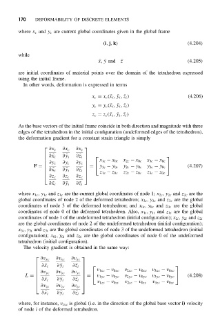
170 DEFORMABILITY OF DISCRETE ELEMENTS
where x c and y c are current global coordinates given in the global frame
(i, j, k) (4.204)
while
x,
y and
z (4.205)
are initial coordinates of material points over the domain of the tetrahedron expressed
using the initial frame.
In other words, deformation is expressed in terms
x c = x c (
x i ,
y i ,
z i ) (4.206)
y c = y c (
x i ,
y i ,
z i )
z c = z c (
x i ,
y i ,
z i )
As the base vectors of the initial frame coincide in both direction and magnitude with three
edges of the tetrahedron in the initial configuration (undeformed edges of the tetrahedron),
the deformation gradient for a constant strain triangle is simply
∂x c ∂x c ∂x c
∂
x i ∂
y i ∂
z i
x 1c − x 0c x 2c − x 0c x 3c − x 0c
∂y c ∂y c ∂y c
F = = y 1c − y 0c y 2c − y 0c y 3c − y 0c (4.207)
∂
x i ∂
y i
∂
z i z 1c − z 0c z 2c − z 0c z 3c − z 0c
∂z c ∂z c ∂z c
∂
x i ∂
y i ∂
z i
where x 1c ,y 1c and z 1c are the current global coordinates of node 1; x 2c ,y 2c and z 2c are the
global coordinates of node 2 of the deformed tetrahedron; x 3c ,y 3c and z 3c are the global
coordinates of node 3 of the deformed tetrahedron; and x 0c ,y 0c and z 0c are the global
coordinates of node 0 of the deformed tetrahedron. Also, x 1i ,y 1i and z 1i are the global
coordinates of node 1 of the undeformed tetrahedron (initial configuration); x 2i ,y 2i and z 2i
are the global coordinates of node 2 of the undeformed tetrahedron (initial configuration);
x 3i ,y 3i and z 3i are the global coordinates of node 3 of the undeformed tetrahedron (initial
configuration); x 0i ,y 0i and z 0i are the global coordinates of node 0 of the undeformed
tetrahedron (initial configuration).
The velocity gradient is obtained in the same way:
∂v xc ∂v xc ∂v xc
∂
x i ∂
y i ∂
z i
v 1xc − v 0xc v 2xc − v 0xc v 3xc − v 0xc
∂v yc ∂v yc ∂v yc
L = = v 1yc − v 0yc v 2yc − v 0yc v 3yc − v 0yc (4.208)
∂
x i ∂
y i
∂
z i v 1zc − v 0zc v 2zc − v 0zc v 3zc − v 0zc
∂v zc ∂v zc ∂v zc
∂
x i ∂
y i ∂
z i
where, for instance, v ixc is global (i.e. in the direction of the global base vector i) velocity
of node i of the deformed tetrahedron.