
Page 183 - The Combined Finite-Discrete Element Method
P. 183
166 DEFORMABILITY OF DISCRETE ELEMENTS
4.8 CONSTANT STRAIN TETRAHEDRON FINITE ELEMENT
To arrive at an efficient discretised distributed potential force contact interaction algorithm
in 3D, as discussed in Chapter 2, it is important to employ the simplest possible geometry
of finite elements. In 3D space this is a four nodded tetrahedron (Figure 4.18).
These simple elements are now also widely used in the finite element method. Special
techniques to avoid problems such as locking are employed. Locking occurs when the
kinematics of nodes comprising the finite element mesh is over-constrained due to the
presence of volumetric rigidity. In elastic problems, locking occurs when incompressible
materials (materials with a Poisson ratio close to 0.5) are analysed. It can also occur
when material nonlinearity such as plasticity is considered, in which case, very often by
default, volumetric plastic strains are zero, which is to say that the material does not
change volume in plastic deformations. The most widely used technique to avoid locking
is to integrate volumetric strain over two or more neighbouring finite elements. With these
modifications, the four node tetrahedron solid finite element can be used for a wide range
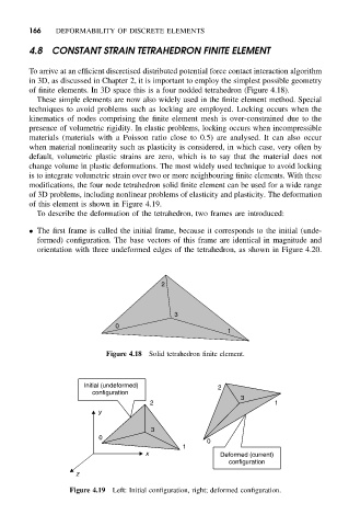
of 3D problems, including nonlinear problems of elasticity and plasticity. The deformation
of this element is shown in Figure 4.19.
To describe the deformation of the tetrahedron, two frames are introduced:
• The first frame is called the initial frame, because it corresponds to the initial (unde-
formed) configuration. The base vectors of this frame are identical in magnitude and
orientation with three undeformed edges of the tetrahedron, as shown in Figure 4.20.
2
3
0
1
Figure 4.18 Solid tetrahedron finite element.
Initial (undeformed) 2
configuration
3
2 1
y
3
0
0
1
x Deformed (current)
configuration
z
Figure 4.19 Left: Initial configuration, right; deformed configuration.