
Page 182 - The Combined Finite-Discrete Element Method
P. 182
CONSTANT STRAIN TETRAHEDRON FINITE ELEMENT 165
To make the first part independent of volume change, further modification by dividing
the stress tensor by the ratio of the increase of edge length of the material element due
√
to the volume change ( | det F|) is adopted, which yields
1 E
˜
T = √ E d + (4.184)
| det F| (1 + v)
1 E 2µ
˜
√ E s + √
| det F| (1 − v) | det F|
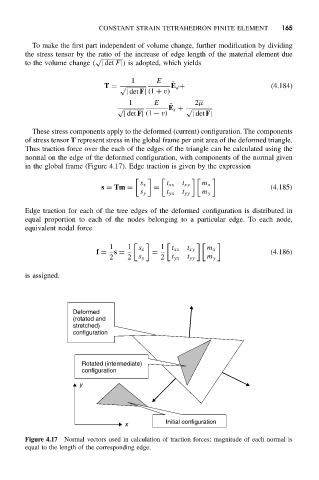
These stress components apply to the deformed (current) configuration. The components
of stress tensor T represent stress in the global frame per unit area of the deformed triangle.
Thus traction force over the each of the edges of the triangle can be calculated using the
normal on the edge of the deformed configuration, with components of the normal given
in the global frame (Figure 4.17). Edge traction is given by the expression
s x t xx t xy m x
s = Tm = = (4.185)
s y t yx t yy m y
Edge traction for each of the tree edges of the deformed configuration is distributed in
equal proportion to each of the nodes belonging to a particular edge. To each node,
equivalent nodal force
1 1 s x 1 t xx t xy m x
f = s = = (4.186)
2 2 s y 2 t yx t yy m y
is assigned.
Deformed
(rotated and
stretched)
configuration
Rotated (intermediate)
configuration
y
Initial configuration
x
Figure 4.17 Normal vectors used in calculation of traction forces; magnitude of each normal is
equal to the length of the corresponding edge.