
Page 184 - The Combined Finite-Discrete Element Method
P. 184
CONSTANT STRAIN TETRAHEDRON FINITE ELEMENT 167
Initial (undeformed)
configuration 2
3
j 2 j k 1
y i
k 3
j 0
0
1
k i x i Deformed (current)
configuration
z
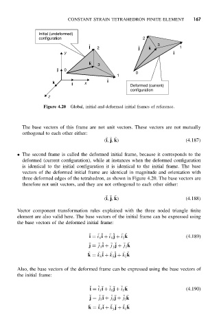
Figure 4.20 Global, initial and deformed initial frames of reference.
The base vectors of this frame are not unit vectors. These vectors are not mutually
orthogonal to each other either:
(i, j, k) (4.187)
• The second frame is called the deformed initial frame, because it corresponds to the
deformed (current configuration), while at instances when the deformed configuration
is identical to the initial configuration it is identical to the initial frame. The base
vectors of the deformed initial frame are identical in magnitude and orientation with
three deformed edges of the tetrahedron, as shown in Figure 4.20. The base vectors are
therefore not unit vectors, and they are not orthogonal to each other either:
(i, j, k) (4.188)
˘ ˘ ˘
Vector component transformation rules explained with the three noded triangle finite
element are also valid here. The base vectors of the initial frame can be expressed using
the base vectors of the deformed initial frame:
˘
˘
i = i ˘x i + i ˘x j + i ˘z k (4.189)
˘
˘
˘
j = j ˘x i + j ˘y j + j ˘z k
˘
˘
˘
k = k ˘x i + k ˘y j + k ˘z k
˘
Also, the base vectors of the deformed frame can be expressed using the base vectors of
the initial frame:
˘
˘
˘
˘
i = i
x i + i
x j + i
x k (4.190)
j = j
x i + j
y j + j
z k
˘
˘
˘
˘
k = k
x i + k
y j + k
z k
˘
˘
˘