
Page 178 - The Combined Finite-Discrete Element Method
P. 178
CONSTANT STRAIN TRIANGLE FINITE ELEMENT 161
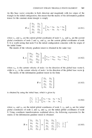
As this base vector coincides in both direction and magnitude with two edges of the
triangle in the initial configuration, this means that the matrix of the deformation gradient
tensor for the constant strain triangle is simply
∂x c ∂x c
∂
x i ∂
y i x 1c − x 0c x 2c − x 0c
F = = (4.161)
∂y c ∂y c y 1c − y 0c y 2c − y 0c
∂
x i ∂
y i
where x 1c and y 1c are the current global coordinates of node 1; x 2c and y 2c are the current
global coordinates of node 2 and x 0c and y 0c are the current global coordinates of node
0. It is worth noting that node 0 in the initial configuration coincides with the origin of
the initial frame.
The matrix of the velocity gradient tensor is obtained in the same way:
∂v xc ∂v xc
∂
x i ∂
y i v 1xc − v 0xc v 2xc − v 0xc
L = = (4.162)
∂v yc ∂v yc v 1yc − v 0yc v 2yc − v 0yc
∂
x i ∂
y i
where v ixc is the current velocity of node i in the direction of the global base vector i,
while is v iyc is the current velocity of node i in the direction of the global base vector j.
The matrix of the deformation gradient tensor in the form
∂x c ∂x c
∂x i ∂y i
F = (4.163)
∂y c ∂y c
∂x i ∂y i
is obtained by using the initial base, which is given by
i x j x x 1i − x 0i x 2i − x 0i
= (4.164)
i y
j y y 1i − y 0i y 2i − y 0i
where x 1i and y 1i are the initial global coordinates of node 1; x 2i and y 2i are the initial
global coordinates of node 2, and x 0i and y 0i are the initial global coordinates of node
0. Using coordinate transformations explained above, the following expression for the
matrix of the deformation gradient tensor is obtained:
∂x c ∂x c ∂x c ∂x c
−1
∂x i ∂y i ∂
x i ∂
y i i x j x
F = = (4.165)
∂y c ∂y c ∂y c ∂y c
i y
j y
∂x i ∂y i ∂
x i ∂
y i