
Page 227 - The Combined Finite-Discrete Element Method
P. 227
210 TEMPORAL DISCRETISATION
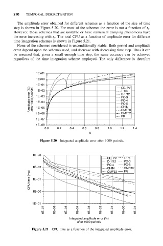
The amplitude error obtained for different schemes as a function of the size of time
step is shown in Figure 5.20. For most of the schemes the error is not a function of t e .
However, those schemes that are unstable or have numerical damping phenomena have
the error increasing with t e . The total CPU as a function of amplitude error for different
time integration schemes is shown in Figure 5.21.
None of the schemes considered is unconditionally stable. Both period and amplitude
error depend upon the schemes used, and decrease with decreasing time step. Thus it can
be assumed that, given a small enough time step, the same accuracy can be achieved
regardless of the time integration scheme employed. The only difference is therefore
1E+01
1E+00
1E−01 CD, PV
Amplitude error (%) after 1000 periods 1E−03 D-1/12
1E−02
T-1/6
PC-3
PC-4
1E−04
PC-5
1E−05
OMF30
1E−06 CHIN
OMF32
FR
1E−07
1E−08
0.0 0.2 0.4 0.6 0.8 1.0 1.2 1.4
K
Figure 5.20 Integrated amplitude error after 1000 periods.
1E+03
CD, PV T-1/6
D-1/12 PC-3
PC-4 PC-5
1E+02 CHIN OMF30
FR
CPU time (ms) 1E+01
OMF32
1E+00
1E−01
1E−07 1E−06 1E−05 1E−04 1E−03 1E−02 1E−01 1E+00 1E+01
Integrated amplitude error (%)
after 1000 periods
Figure 5.21 CPU time as a function of the integrated amplitude error.