
Page 79 - The Combined Finite-Discrete Element Method
P. 79
62 PROCESSING OF CONTACT INTERACTION
once the force on the centre of the target tetrahedron has been obtained, it is replaced
by the equivalent forces at the nodes of the target tetrahedron. The same is done with
the contact force assigned to the centre of the contactor tetrahedron.
It is also worth mentioning that each tetrahedron is considered twice, once as a con-
tactor and once as a target.
There are a number of ways to numerically execute the tasks listed above. The most
critical path of the algorithm is the intersection of the target sub-tetrahedron and the base
of the contactor sub-tetrahedron. It is best performed in two steps. First, the intersection
points of the edges of the target sub-tetrahedron with the plane containing the base of
the contactor sub-tetrahedron are found. The result is a convex polygon. The intersection
of this polygon with the triangular base of the contactor sub-tetrahedron is therefore a
2D problem.
2.6.3 Physical interpretation of the penalty parameter
As explained earlier, the maximum allowed penetration is a function of the size of finite
elements at the place of contact and penalty parameter p, which can be different for
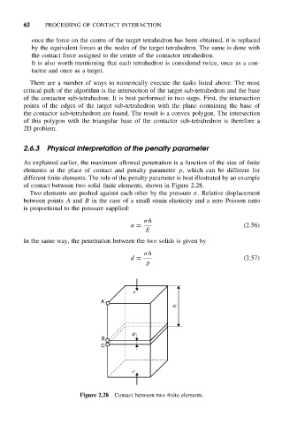
different finite elements. The role of the penalty parameter is best illustrated by an example
of contact between two solid finite elements, shown in Figure 2.28.
Two elements are pushed against each other by the pressure σ. Relative displacement
between points A and B in the case of a small strain elasticity and a zero Poisson ratio
is proportional to the pressure supplied:
σh
u = (2.56)
E
In the same way, the penetration between the two solids is given by
σh
d = (2.57)
p
s
A
h
d
B
C
s
Figure 2.28 Contact between two finite elements.