
Page 76 - The Combined Finite-Discrete Element Method
P. 76
POTENTIAL CONTACT FORCE IN 3D 59
3
4
1
2
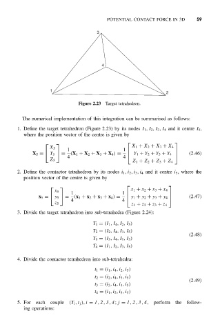
Figure 2.23 Target tetrahedron.
The numerical implementation of this integration can be summarised as follows:
1. Define the target tetrahedron (Figure 2.23) by its nodes I 1 ,I 2 ,I 3 ,I 4 and it centre I 5 ,
where the position vector of the centre is given by
X 1 + X 2 + X 3 + X 4
X 5
1
1
X 5 = Y 5 = (X 1 + X 2 + X 3 + X 4 ) = (2.46)
4 4 Y 1 + Y 2 + Y 3 + Y 4
Z 5
Z 1 + Z 2 + Z 3 + Z 4
2. Define the contactor tetrahedron by its nodes i 1 ,i 2 ,i 3 ,i 4 and it centre i 5 ,where the
position vector of the centre is given by
x 1 + x 2 + x 3 + x 4
x 5
1
1
x 5 = y 5 = (x 1 + x 2 + x 3 + x 4 ) = y 1 + y 2 + y 3 + y 4 (2.47)
4 4
z 5
z 1 + z 2 + z 3 + z 4
3. Divide the target tetrahedron into sub-tetrahedra (Figure 2.24):
T 1 = (I 1 ,I 4 ,I 2 ,I 5 )
T 2 = (I 2 ,I 4 ,I 3 ,I 5 )
(2.48)
T 3 = (I 3 ,I 4 ,I 1 ,I 5 )
T 4 = (I 1 ,I 2 ,I 3 ,I 5 )
4. Divide the contactor tetrahedron into sub-tetrahedra:
t 1 = (i 1 ,i 4 ,i 2 ,i 5 )
t 2 = (i 2 ,i 4 ,i 3 ,i 5 )
(2.49)
t 3 = (i 3 ,i 4 ,i 1 ,i 5 )
t 4 = (i 1 ,i 2 ,i 3 ,i 5 )
5. For each couple (T i ,t j ), i = 1, 2, 3, 4; j = 1, 2, 3, 4, perform the follow-
ing operations: