
Page 164 - The Master Handbook Of Acoustics
P. 164
139
REVERBERATION
Pink
noise Power
gen. amplifier
Tape B&K 2215
recorder SLM*
A
*With octave filters
Tape B&K 2215 B&K 2305
recorder SLM* Level
recorder
B
FIGURE 7-6
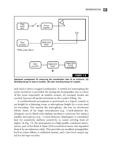
Equipment arrangement for measuring the reverberation time of an enclosure. (A)
Recording decays on tape on location. (B) Later recording decays for analysis.
and used to drive a rugged loudspeaker. A switch for interrupting the
noise excitation is provided. By aiming the loudspeaker into a corner
of the room (especially in smaller rooms), all resonant modes are
excited, because all modes terminate in the corners (Chap. 15).
A nondirectional microphone is positioned on a tripod, usually at
ear height for a listening room, or microphone height for a room used
for recording. The smaller the microphone, the less its directional
effects. Some of the larger microphones (e.g., 1-inch-diameter dia-
phragms) can be fitted with random incidence correctors, but using a
1
smaller microphone (e.g., 2-inch-diameter diaphragm) is considered
best for essentially uniform sensitivity to sound arriving from all
angles. In Fig. 7-6, the microphone is a high-quality condenser micro-
phone, part of the Brüel & Kjaer 2215 sound-level meter, but separated
from it by an extension cable. This provides an excellent preamplifier,
built-in octave filters, a calibrated system, and a line-level output sig-
nal for the tape recorder.