
Page 175 -
P. 175
The Practical Pumping Handbook ....................
9.2.3 Pump discharge head
The discharge head can be either a
fabricated part of a casting that
provides a base from which the
pump is suspended and on which
the driver is mounted. It also
directs the flow from the vertical
column to a horizontal flanged
discharge nozzle that will be
connected to the system. The
discharge head is fitted with a
stuffing box or seal chamber
through which the line shaft
passes to connect with the driver.
Depending on the application,
either packing or mechanical seals
can be used. When an enclosing
tube is used, a tension nut is fitted
to keep the tube under tension
and to hold it straight.
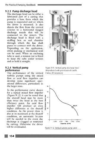
9.2.4 Vertical pump Figure 9.11. Vertical pump discharge head
performance (Reproduced with permission of Goulds
The performance of the vertical Pumps, ITT Industries)
turbine pumps using the mixed
flow or axial flow impellers can
develop some significant oper-
ational differences, particularly in
the larger sizes.
In the performance curve shown
for a typical mixed flow impeller ~0
(Figure 9.12) it can be noted that
the shutoff head may be more ~, 40
than twice the head at the best
u
efficiency point. An axial flow ] 30
g
impeller will produce an even,.,
higher difference at the shutoff ~_ 20
condition. As the power draw is
also at its maximum at the shutoff ~0
condition, an automatic by-pass
will be needed in the event the
I I I I I
discharge is clogged or restricted 2, 500 5, 000 7, 500 1 O, 000 12, 500
by valving. Otherwise the driver Capacity - G.P.M.
will be overloaded. Figure 9.12: Vertical turbine pump curve
m 154 .........