
Page 170 -
P. 170
......................... Special Pumps
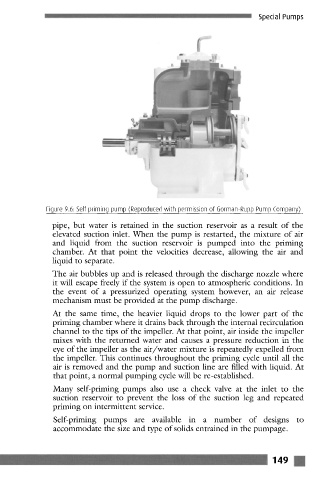
Figure 9.6: Self priming pump (Reproduced with permission of Gorman-Rupp Pump Company)
pipe, but water is retained in the suction reservoir as a result of the
elevated suction inlet. When the pump is restarted, the mixture of air
and liquid from the suction reservoir is pumped into the priming
chamber. At that point the velocities decrease, allowing the air and
liquid to separate.
The air bubbles up and is released through the discharge nozzle where
it will escape freely if the system is open to atmospheric conditions. In
the event of a pressurized operating system however, an air release
mechanism must be provided at the pump discharge.
At the same time, the heavier liquid drops to the lower part of the
priming chamber where it drains back through the internal recirculation
channel to the tips of the impeller. At that point, air inside the impeller
mixes with the returned water and causes a pressure reduction in the
eye of the impeller as the air/water mixture is repeatedly expelled from
the impeller. This continues throughout the priming cycle until all the
air is removed and the pump and suction line are filled with liquid. At
that point, a normal pumping cycle will be re-established.
Many self-priming pumps also use a check valve at the inlet to the
suction reservoir to prevent the loss of the suction leg and repeated
priming on intermittent service.
Self-priming pumps arc available in a number of designs to
accommodate the size and type of solids entrained in the pumpagc.
' .................. - ........... iiiiiiiiiiiiiiiiiiiii_ - i 149