
Page 169 -
P. 169
The Practical Pumping Handbook
,",r [
m
I ~riming
Tank
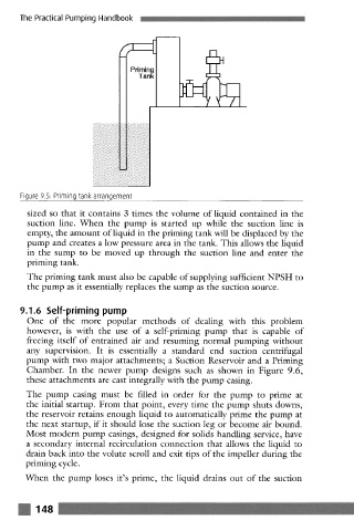
Figure 9.5: Priming tank arrangement
sized so that it contains 3 times the volume of liquid contained in the
suction line. When the pump is started up while the suction line is
empty, the amount of liquid in the priming tank will be displaced by the
pump and creates a low pressure area in the tank. This allows the liquid
in the sump to be moved up through the suction line and enter the
priming tank.
The priming tank must also be capable of supplying sufficient NPSH to
the pump as it essentially replaces the sump as the suction source.
9.1.6 Self-priming pump
One of the more popular methods of dealing with this problem
however, is with the use of a self-priming pump that is capable of
freeing itself of entrained air and resuming normal pumping without
any supervision. It is essentially a standard end suction centrifugal
pump with two major attachments; a Suction Reservoir and a Priming
Chamber. In the newer pump designs such as shown in Figure 9.6,
these attachments are cast integrally with the pump casing.
The pump casing must be filled in order for the pump to prime at
the initial startup. From that point, every time the pump shuts downs,
the reservoir retains enough liquid to automatically prime the pump at
the next startup, if it should lose the suction leg or become air bound.
Most modern pump casings, designed for solids handling service, have
a secondary internal recirculation connection that allows the liquid to
drain back into the volute scroll and exit tips of the impeller during the
priming cycle.
When the pump loses it's prime, the liquid drains out of the suction
148