
Page 165 -
P. 165
The Practical Pumping Handbook .............................................
In this pump design, the liquid is
not pumped through the column
assembly. The discharge nozzle on
the pump casing is horizontal and
discharges into an elbow that
directs the liquid through a
vertical pipe to an above grade
connection at the soleplate. This
dual connection of the discharge
pipe and column to the sole plate
provides additional rigidity for the
pump to help withstand the effect
of the radial loading in the pump
casing.
As the operation of the pump
usually depends on the level of
liquid in the sump, a variety of
float switches can be used for
automatic on/off control. In the
event that the level in the sump is
likely to draw down below the
level of the impeller, a tail pipe can
be bolted to the suction flange
that will allow the pump to
operate under these conditions.
A drainage type of application
constitutes the vast majority of
services for which these pumps are
purchased. In such conditions
they should not be considered or
treated as a heavy duty pump.
However, a number of manu-
facturers have dramatically
upgraded the design for operation
in chemical process services where
the liquid being pumped is so
aggressive that safety standards
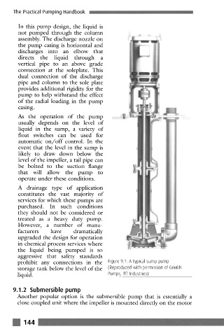
prohibit any connections in the Figure 9.1. A typical sump pump
storage tank below the level of the (Reproduced with permission of 6oulds
liquid. Pumps, ITT Industries)
9.1.2 Submersible pump
Another popular option is the submersible pump that is essentially a
close coupled unit where the impeller is mounted directly on the motor
! 144