
Page 168 -
P. 168
[[I i ..... I .... Ill i IIIIHI " Special Pumps
However, the one that is most commonly used in drainage sump
applications is the air operated double diaphragm pump.
This pump style is essentially two pumps in one where one is on the
suction cycle while the other is on the discharge cycle. Compressed air
is delivered through the air shuttle valve and is directed alternately from
one diaphragm to the other. As it pressurizes one diaphragm, it
simultaneously exhausts the air from the other.
When a diaphragm is pressurized it moves inwards towards the pum-
ping cavity and raises the pressure in that cavity. This closes the suction
valve against the lower suction line pressure, and opens the discharge
valve to force the liquid out of the pump. As the diaphragm moves out
from the pump cavity, the pressure is lowered, thus allowing the suction
valve to open and the discharge valve to close. This movement creates a
low pressure area in the pump cavity as the air is forced out, thus
allowing the liquid to move up the suction line into the pump.
9.1.5 Horizontal centrifugal pump
A horizontal centrifugal pump can be used on a suction lift application,
but only with some assistance to ensure that it is always primed prior to
startup.
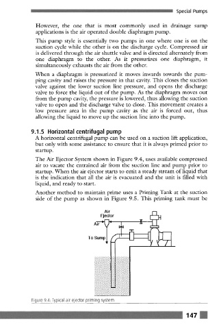
The Air Ejector System shown in Figure 9.4, uses available compressed
air to vacate the entrained air from the suction line and pump prior to
startup. When the air ejector starts to emit a steady stream of liquid that
is the indication that all the air is evacuated and the unit is filled with
liquid, and ready to start.
Another method to maintain prime uses a Priming Tank at the suction
side of the pump as shown in Figure 9.5. This priming tank must be
Air
Ejector
To Sump ~ - r 0
'.)'.:.i~ :.-'.7.:.".:::'.'_.'.".:" "._':.".i-
9 .7.'..~ :..-'..~.:..~.:.-.:...'.:...'-.--..
,'}.-..:.-j
.....,.:...
...-..:-
.:-.:...
.:....-...
9 :.-.:....
":."'::" t.- "-i-'Z;:: ::::2-'.: ::'-':'..
9 :}..:..'....;..:. :.;.;~;.,
9 :....:- ..::::.-:::..::::.
9 ..-'...-'..-. .............
9 ::-..-'. ..... .., .., .., .., ..,
9 .-4..< .-:.::.:...:._.:.....:.:....
Figure 9.4. Typical air ejector priming system
147