
Page 56 -
P. 56
...................................................... System Hydraulics
3.3 Basic elements of pump system design
In designing any kind of pumping system, the first requirement is to
determine the speed at which the task must be performed. In other
words, the flow needed through the system. In some systems, the flow
rate will be determined by production requirements or by other process
considerations such as the flow rate needed to achieve the necessary
temperature transfer in a liquid flowing through a heat exchanger. For
the sake of this exercise, let us consider a batch process system where
the average flow rate can be calculated by dividing the volume to be
transferred, by the time allowed for that transfer.
The next requirement to be considered is how to overcome all the
factors which hinder the movement of the liquid from one point to
another in the system. These are primarily Gravity and Friction and we
will deal with them separately.
3.3.1 Gravity and static head
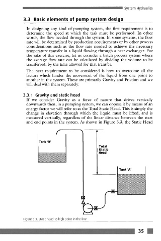
If we consider Gravity as a force of nature that drives vertically
downwards then, in a pumping system, we can oppose it by means of an
energy factor we will refer to as the Total Static Head. This is simply the
change in elevation through which the liquid must be lifted, and is
measured vertically, regardless of the linear distance between the start
and end points in the system. As shown in Figure 3.3, the Static Head
f
Tank 'B'
Total
Static
Head
Tank 'A'
,,...4 =
Figure 3.3. Static head to high point in the line
3s m