
Page 58 -
P. 58
System Hydraulics
9 the Piping
9 the Valves and Fittings, and
9 Other Equipment, such as filters, heat exchangers, etc.
The Friction Losses in piping can
most readily be obtained from the
Friction Loss Tables available from
a variety of sources such as the
Standards of the Hydraulic In- Friction /
stitute. For benefit of the reader,
many of these tables are repro-
duced in Chapter 14 of this book.
Tables are also available to identify
the losses through the more
common pipe fittings and valve Q
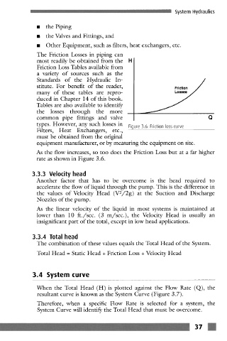
types. However, any such losses in Figure 3.6: Friction loss curve
Filters, Heat Exchangers, etc.,
must be obtained from the original
equipment manufacturer, or by measuring the equipment on site.
As the flow increases, so too does the Friction Loss but at a far higher
rate as shown in Figure 3.6.
3.3.3 Velocity head
Another factor that has to be overcome is the head required to
accelerate the flow of liquid through the pump. This is the difference in
the values of Velocity Head (V2/2g) at the Suction and Discharge
Nozzles of the pump.
As the linear velocity of the liquid in most systems is maintained at
lower than 10 ft./see. (3 m/see.), the Velocity Head is usually an
insignificant part of the total, except in low head applications.
3.3.4 Total head
The combination of these values equals the Total Head of the System.
Total Head = Static Head + Friction Loss + Velocity Head
3.4 System curve
When the Total Head (H) is plotted against the Flow Rate (Q), the
resultant curve is known as the System Curve (Figure 3.7).
Therefore, when a specific Flow Rate is selected for a system, the
System Curve will identify the Total Head that must be overcome.
~" ' 37 m