
Page 62 -
P. 62
System Hydraulics
X
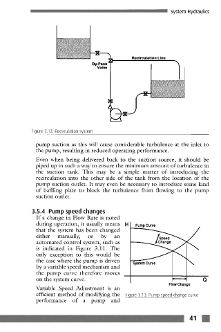
Recirculation Line
1
By-Pass
Valve
Figure 3.12. Recirculation system
pump suction as this will cause considerable turbulence at the inlet to
the pump, resulting in reduced operating performance.
Even when being delivered back to the suction source, it should be
piped up in such a way to ensure the minimum amount of turbulence in
the suction tank. This may be a simple matter of introducing the
recirculation into the other side of the tank from the location of the
pump suction outlet. It may even be necessary to introduce some kind
of baffling plate to block the turbulence from flowing to the pump
suction outlet.
3.5.4 Pump speed changes
If a change in Flow Rate is noted
during operation, it usually means Pump Curve
that the system has been changed
either manually, or by an
automated control system, such as
is indicated in Figure 3.11. The
only exception to this would be
the case where the pump is driven System Curve \
by a variable speed mechanism and
the pump curve therefore moves
on the system curve. Q
Flow Change
Variable Speed Adjustment is an
efficient method of modifying the Figure 3.13. Pump speed change curve
performance of a pump and
m
IIllIll ................ ~ ......................................................................................................................................................................................... :::::::: .................................................... ~ ~ 41