
Page 66 -
P. 66
. . . . System Hydraulics
multiplied by the Velocity Head (from the Friction Loss tables) to
provide the Friction Loss for that particular fitting. Consequently, the
value of the friction loss for each fitting must be calculated individually.
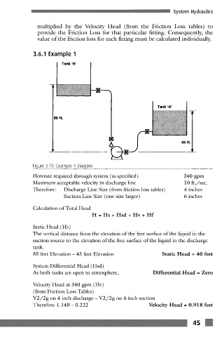
3.6.1 Example 1
Tank 'B'
X
Tank 'A'
80 ft.
q~e
45 f
Figure 3.19: Example 1 diagram
Flowrate required through system (as specified) 340 gpm
Maximum acceptable velocity in discharge line 10 ft./sec.
Therefore: Discharge Line Size (from friction loss tables) 4 inches
Suction Line Size (one size larger) 6 inches
Calculation of Total Head
H = Hs + Hsd + Hv + Hf
Static Head (Hs)
The vertical distance from the elevation of the free surface of the liquid in the
suction source to the elevation of the free surface of the liquid in the discharge
tank.
85 feet Elevation- 45 feet Elevation Static Head = 40 feet
System Differential Head (Hsd)
As both tanks are open to atmosphere, Differential Head = Zero
Velocity Head at 340 gpm (Hv)
(from Friction Loss Tables)
V2/2g on 4 inch discharge- V2/2g on 6 inch suction
Therefore 1.140- 0.222 Velocity Head -- 0.918 feet