
Page 63 -
P. 63
The Practical Pumping Handbook :ii:i: -iiiiii : :: : :iiiiiii:i iiiiiiiiiii::ii:: ii:iiii:i-iiiii ....... i ........ i ............. ,i-i ........ ii-i .......... i ........
system, and can be achieved by a variety of mechanical or electrical
drives. The Variable Frequency Drive is one of the most commonly
used items in many plants.
When frequent adjustment is needed to the output of the pump, the
traditional method of throttling the discharge valve absorbs a significant
amount of friction which translates into energy losses that can be
identified in increased heat and excessive wear in the valve. It also
restrains the pump to operate at a lower and (usually) a less efficient
point on the performance curve, thus compounding the energy loss.
A speed reduction to lower the pump output will frequently have the
pump operating with only a very minor reduction in efficiency.
Computer controlled speed change systems are now available that
permits the end user to preset the required pumping condition (either
flow rate or head) and the Variable Frequency Drive will adjust the
pump speed automatically to meet all changes in system demand.
3.5.5 Series and parallel operation
In many instances, two or more pumps are required to operate
together, either in Series or in Parallel. In a Series Operation, each of
the two pumps operate at the same flow rate, but share the head, while
in a Parallel Operation, each of the two pumps operate at the same
head, but share the flow rate.
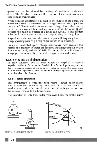
3.5.5.1 Series operation
This arrangement is frequently used where a larger pump cannot
operate with the NPSH being made available from the system. A
smaller pump is therefore installed upstream of the larger one to boost
the Suction Pressure to the larger pump.
It is important to note that, under these conditions, the smaller pump
Main
Booster
Q
Figure 3.14: Series pump diagram Figure 3.15: Series pump curve
m 42