
Page 68 -
P. 68
........................................ System Hydraulics
'B'
T
0 ft. Tank 'A'
A~,~ 10 .,~
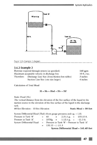
Figure 3.20: Example 2 diagram
3.6.2 Example 2
Flowrate required through system (as specified) 160 gpm
Maximum acceptable velocity in discharge line 10 ft./sec.
Therefore: Discharge Line Size (from friction loss tables) 3 inches
Suction Line Size (one size larger) 4 inches
Calculation of Total Head
H = Hs + Hsd + Hv + Hf
Static Head (Hs)
The vertical distance from the elevation of the free surface of the liquid in the
suction source to the elevation of the free surface of the liquid in the discharge
tank.
60 feet Elevation- 10 feet Elevation Static Head = 50 feet
System Differential Head (Hsd) (from gauge pressures and s.g. = 1.0)
Pressure in Tank 'B' = 65 x 2.31/s.g. = 150.15 ft.
Pressure in Tank'A' = 10'Hg x 1.13/s.g. = -11.3 ft.
System Differential Head = Pressure in Tank 'B'- Pressure in Tank 'A'
= 150.15-(-)~1.3
System Differential Head = 161.45 feet
m
/17